Mine Earthing and Low-Voltage Protection: Making Cable and Relay Work Together
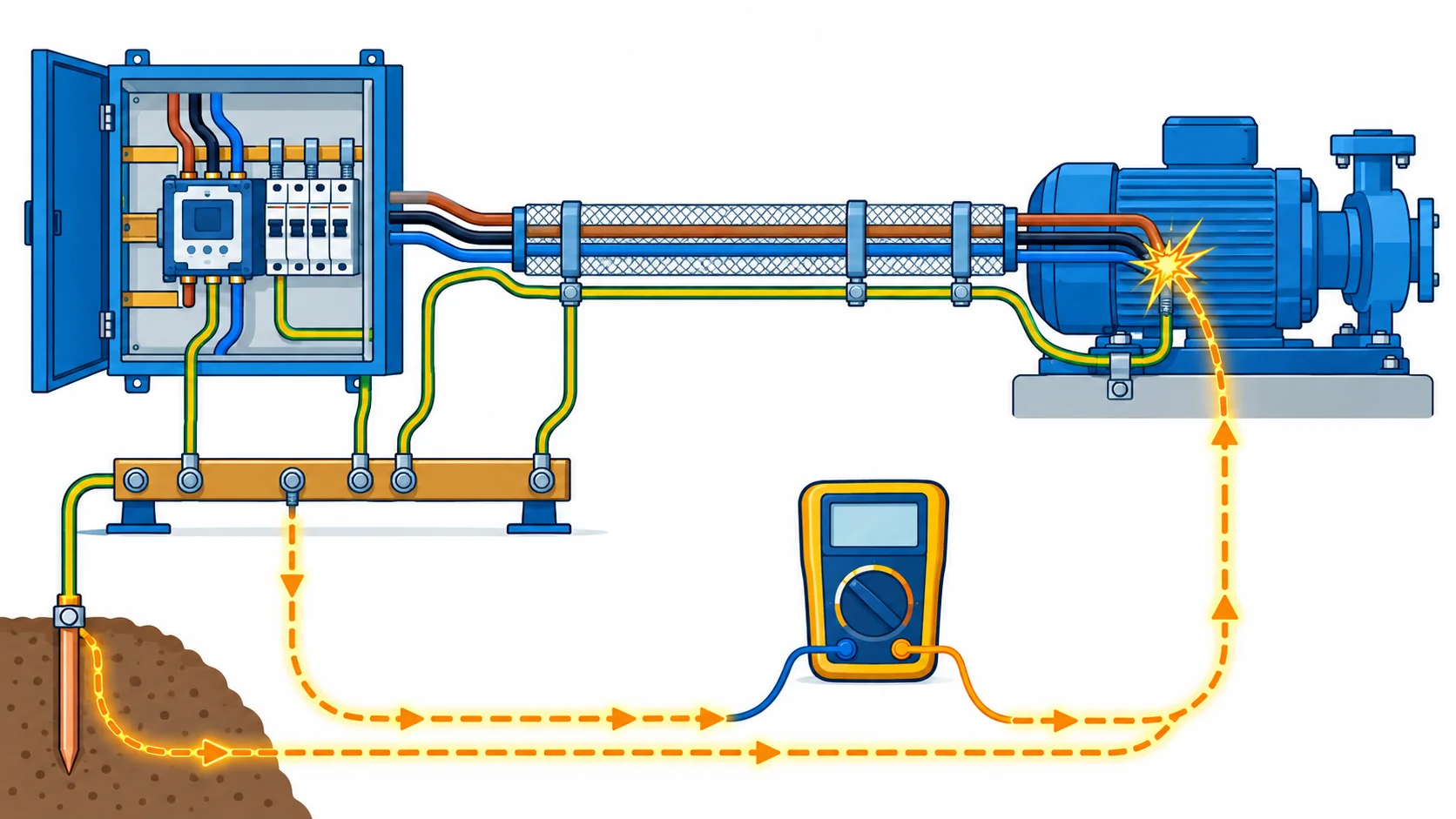
Quick Answer: Mine earthing is not an accessory to a cable order, it is part of what the cable has to do. The protective conductor size, the screen arrangement and the run length together decide whether the earth fault relay sees enough current to trip. Buyers who treat earthing as an installation detail later discover that the protection cannot be set to operate on the cable they bought.
Introduction
On a mine, a cable is bought into a protection scheme rather than onto a load. That is a different starting point from a plant, where the earth path is often incidental. In a gassy roadway or a wet face, the earth path and the leakage detection are what stop a damaged cable from becoming an ignition source, and they are designed rather than assumed.
The consequence for procurement is that the cable cross-section, the conductor arrangement and the screen are all inputs to the protection calculation. A specification that names a cross-section without naming the earth loop requirement cannot be checked, and a supplier who is not told the loop requirement cannot help. This note is about the interface between the two, and about the decisions a buyer can usefully freeze before the order.
Why the Cable Is Part of the Protection Scheme
Fault current depends on the loop, not on the transformer alone. The current that flows in an earth fault is limited by the impedance of the whole loop: the supply, the phase conductor, the earth path and the return. A long run with a small protective conductor has a high loop impedance and a low fault current, and a low fault current may not operate the device quickly enough.
The earth path is made of cable parts. On many constructions the protective conductor is a core, and on others it is the screen or the armour. Each of those has a different impedance and a different tolerance for damage, and each has a different behaviour when the cable is dragged, bent or corroded.
Leakage detection reads the cable’s condition. Earth leakage and continuity monitoring systems measure insulation resistance and earth path continuity. Their settings have to be compatible with the cable’s normal leakage and with the run length, or the mine gets either nuisance trips or a system that never operates.
The Five Interfaces Between Cable and Protection
Most coordination problems on a mine sit at one of these five points.
| Interface | What Depends On It | What to Specify | Evidence to Demand | Cost and Lead Time | How It Fails |
|---|---|---|---|---|---|
| Earth fault loop impedance | Whether the device trips fast enough on a fault | Conductor and protective conductor sizes, plus the run length | A loop impedance calculation for the worst run | Larger conductor costs copper; the calculation is free | A fault that does not operate the device at all |
| Protective conductor sizing | The earth path survives a fault without damage | Core, screen or armour arrangement, with the size stated | Sizing calculation against the device's let through energy | Modest cost, and it may change the construction | An earth path that burns out during the fault it was meant to clear |
| Earth continuity monitoring | The machine stops before a broken earth becomes dangerous | Pilot or monitoring core arrangement matching the scheme | Continuity test after installation, end to end | Low cost, high consequence if the scheme is not matched | A monitoring circuit that reads healthy with a broken path |
| Earth leakage and lockout | Energising is prevented when insulation is low | Cable leakage characteristics, run length and the setting range | Insulation resistance values, and a trip test on site | No direct cable cost, but it constrains the setting | Nuisance tripping on long runs, or a lockout that never operates |
| Bonding of screens and structures | The earth path is continuous and low impedance | Bonding points, gland types and the arrangement at each end | Bonding continuity and impedance measurements | Small cost, and it is usually an installation issue | Circulating currents, noise and a high impedance path |
Earth Fault Loop Impedance and Cross-Section
The loop impedance calculation is where cable selection and protection setting meet, and it is worth doing before the cable is ordered rather than after it is installed.
Long runs are where it bites. A feeder two kilometres down a roadway has a loop impedance dominated by the cable, not by the supply. Increasing the length without reviewing the calculation is how a mine ends up with a feeder whose fault current is below the device’s operating threshold. The fix is a larger cross-section, a parallel earth path or a protection scheme that is designed for a lower current.
The protective conductor is part of the answer. The protective conductor has to carry the fault current for the duration of the fault without being damaged, and its size follows from the device’s operating energy rather than from a table alone. Where the protective path is a screen or an armour, its effective cross-section and its joints both matter, which is a point in favour of a proper core where the duty is severe. Our note on armoured and unarmoured cable sets out where each is appropriate.
Derating interacts with protection too. A cable that is derated for grouping or ambient carries less current, which changes the device settings and the thermal behaviour during a fault. Our note on cable derating factors covers the derivation, and the point here is that the derated current should be in the same document as the protection settings rather than in a separate one.
Put the calculation in the enquiry. A supplier who is given the loop impedance requirement can propose a construction that meets it. A supplier who is given only a load current is quoting into a gap, and the gap is usually filled at commissioning by someone adjusting a protection setting to fit whatever cable arrived.
Earth Continuity Monitoring and Earth Leakage Lockout
These two schemes are often discussed as one, and they do different jobs.
Earth continuity monitoring checks the path. It watches the integrity of the earth conductor or pilot circuit and stops the machine if the path is broken, typically before an operator can be exposed to a live frame. It depends on a dedicated conductor, which is why the pilot core arrangement has to match the machine. Our note on grounding for moving cable covers how the path is arranged on mobile machines.
Earth leakage lockout checks the insulation. It measures or infers leakage current and prevents energising when insulation resistance is too low, or trips when leakage rises during operation. Its setting has to sit above the normal leakage of the installation and below the level that is dangerous, which means the normal leakage of the cable and the run length both matter.
Long runs push the two schemes in opposite directions. A long run increases normal capacitive leakage, which argues for a higher setting, while the same length reduces fault current, which argues for a lower one. That is the coordination problem in one sentence, and it is resolved by calculation rather than by adjusting the relay until the trips stop. Where a powered substation is set close to the load to shorten the run, the problem is being solved at source; the option is described in our note on the prefabricated substation for mining.
Where monitoring and control conductors carry the schemes, they should be screened and routed separately from power conductors. The screened control cable range covers the constructions used for that, and the standards that apply to the switchgear end are outlined in our note on medium voltage standards where the installation extends into that range.
What to Freeze Before the RFQ Goes Out
| Decision | What to State | Evidence to Attach | Cost of Leaving It Open |
|---|---|---|---|
| Worst run | The longest run and its loop impedance requirement | A loop impedance calculation for that run | A feeder whose fault current cannot operate the device |
| Earth path type | Core, screen or armour, with the effective size | A sizing calculation against the device energy | An earth path damaged by the fault it was meant to clear |
| Monitoring scheme | Continuity monitoring or leakage lockout, with the arrangement | A machine or switchgear drawing showing the circuit | A scheme that reads healthy with a broken path |
| Leakage setting range | The expected normal leakage and the setting band | Insulation resistance values for the run | Nuisance trips, or a lockout that never operates |
| Bonding arrangement | Bonding points, gland types and the arrangement at each end | A bonding schedule with measured continuity | Circulating currents and a high impedance earth path |
| Commissioning tests | Loop impedance, insulation resistance and a trip test | A test plan with the acceptance values | A protection system that has never been proven to operate |
Commissioning and Routine Testing
An earthing and protection scheme that has not been tested is a scheme nobody can rely on, and the tests are simple enough to specify in the purchase order.
Measure the loop impedance on the installed run. A measured value that is higher than the calculated one usually points at a joint, a bonding point or a protective conductor that was not installed as drawn. Finding it at commissioning is cheap; finding it after a fault is not.
Prove the device operates. A trip test on the earth leakage device confirms that the setting and the mechanism both work. Our note on in service cable testing covers the routine tests that sit alongside this, and our note on insulation resistance testing covers the measurement conditions that make the insulation readings meaningful on a wet mine.
Test the continuity path after every intervention. Any work that disturbs a gland, a joint or a bonding point should end with a continuity check. That is the single highest value routine in this whole subject, and it costs minutes. The checks are set out in our note on grounding and bonding verification.
When a Bigger Cable Is Not the Answer
When the trip is a setting problem. A feeder tripping on earth leakage well above its expected leakage is telling you about the setting, the insulation or a joint. Increasing the cross-section changes the loop impedance and does nothing for a leakage problem.
When the earth path was never continuous. A high loop impedance on a run that was calculated as acceptable is a bonding or termination fault. Replacing the cable because the earth path is broken is an expensive way to find a gland.
When the leakage is normal but the setting is tight. Long runs have capacitance and long runs have leakage, and a setting borrowed from a short installation will trip. Adjust the setting against a calculation rather than against the nuisance.
When the real issue is distance. Where a run has grown far beyond what the protection scheme can cover economically, a larger cable is one answer and a closer substation is often a better one. Compare the two on the cost of the copper against the cost of the substation and the cable it saves.
When earthing is treated as a site detail. A cable ordered without the loop requirement is a cable whose protection has to be designed around it afterwards. Naming the requirement in the enquiry costs nothing and is the difference between a coordinated scheme and a set of compromises.
RFQ Checklist
- The longest run identified, with its measured route length
- Earth fault loop impedance requirement for that run, stated as a value
- Protective conductor type and effective size, with the sizing calculation
- Screen or armour arrangement where it forms part of the earth path
- Earth continuity monitoring scheme and the pilot core arrangement required
- Earth leakage setting range, and the normal leakage of the installation
- Insulation level and prospective fault current at each distribution point
- Derated current included in the same document as the protection settings
- Bonding points and gland types, matched to the cable construction
- Separation of monitoring and control conductors from power conductors
- Loop impedance, insulation resistance and trip tests in the commissioning plan
- Continuity check required after every intervention, written into the procedure
- Test results and as-built drawings kept with the mine’s electrical records
Conclusion
Mine earthing is a design input to the cable order, not a detail added at installation. State the loop impedance requirement, size the protective conductor against the device, match the monitoring scheme to the machine and prove the whole thing at commissioning.
Kexingyu Cable Group (KXYE) has supplied electrical cable from Quanzhou since 1996, including the screened, armoured and monitoring constructions that mine protection schemes depend on, along with the glands and terminations that complete the earth path. Send the loop impedance requirement, the monitoring scheme and the run lengths, and we will come back with the constructions and protective conductor arrangements that satisfy the calculation, the test evidence that applies, and a delivery plan against your commissioning date. The fastest route is a request for quotation.