
Servo Cable Explained: Power, Encoder and Brake Cores in One Cable
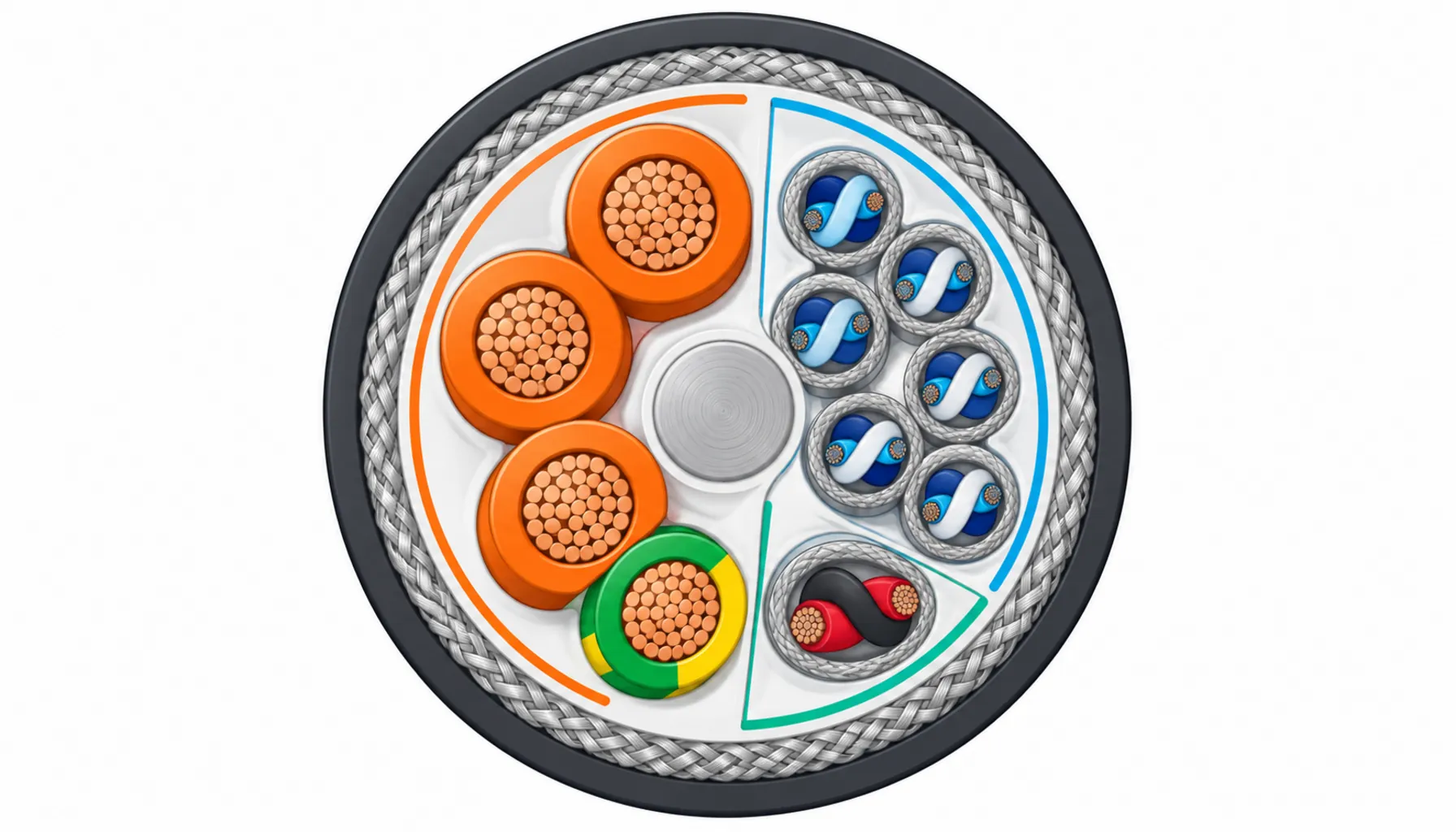
Quick Answer: A servo cable bundles motor power, encoder feedback and brake cores into one motion-rated construction — sized for drive switching noise, shielded against its own EMC, and built to flex with the axis it feeds.
A servo axis is a conversation happening thousands of times a second: the drive commands current, the motor turns, the encoder reports back, the drive corrects. The cable between drive and motor carries every part of that conversation — muscle and nerves in one loom. Get the cable right and the axis is boring, in the best sense of the word. Get it wrong and you inherit the classic symptoms: position noise nobody can reproduce on the bench, drives that trip on overcurrent on humid mornings, feedback glitches that come and go with the machine’s mood. This article explains what is actually inside a servo cable, why servo drives are uniquely hard on their wiring, when a combined cable beats separate runs, and the wiring discipline that keeps an axis quiet for its design life.
Introduction
Servo systems differ from ordinary motor circuits in one fundamental way: the loop is closed through the cable. A standard induction motor fed from a starter does its job whether or not any signal returns; a servo motor without clean feedback is a very expensive heater. That is why servo wiring is a system problem rather than a cable-buying problem. The power circuit carries switched, high-frequency-laden current that radiates; the feedback circuit carries millivolt-level signals that receive; and both live a few millimeters apart inside the same jacket, bending together millions of times. Engineering those two realities to coexist is the whole craft of servo cable design.
The hardware around the cable matters here too. Servo drives are the sophisticated end of the motor-control family that runs from the simple switching devices compared in VFD versus soft starter up to full motion controllers, and they are increasingly packaged in the modular cabinets described in the MCC panel guide. But no drive compensates for a cable that was never designed for the job — and the failure record shows that plainly, in the same patterns catalogued in the common causes of cable failure.
What a Servo Cable Carries
Open a typical combined servo cable and you find three circuits sharing one jacket, each with its own requirements:
Power cores. Three phase conductors — U, V, W — plus a protective earth, sized for the motor’s continuous and peak current. These are not gentle sinusoidal supplies: the drive outputs PWM voltage that arrives at the motor as steep-edged pulses, which is why insulation quality and the drive-to-motor distance matter more here than in a standard feeder. Voltage drop at full travel belongs in the same calculation as it does for any power run, and the sizing habits from the cable size selection guide carry over directly.
Feedback cores. A separate, shielded bundle of small twisted pairs carrying encoder or resolver signals — incremental, absolute, sometimes both plus temperature sensing from the motor windings. These pairs are the quiet guests in a loud house: millivolt signals trying to describe rotor position while millivolt-scale interference would be enough to corrupt them.
Brake cores. Most servo motors carry a holding brake, fed at 24 V DC, that engages when power drops. The brake pair shares the cable because it shares the journey — and because disconnecting it from the loop would mean a dropped load the day someone re-routes “just the power cable.”
Wrap all of this in a motion-grade construction — fine short-lay stranding, a strain-bearing center, an overall braid shield, often individual screens on the feedback pairs, and a PUR or equivalent jacket — and you have the product the catalog calls a servo cable.
Why Servo Drives Are Hard on Cable
Three physical realities make servo wiring harder than the same horsepower in a standard circuit. First, steep voltage edges: PWM switching sends high-frequency energy down the power cores, and long or poor-quality motor cables reflect some of it back, stressing insulation at the motor terminals and radiating along the run. Second, broadband noise: the same switching is a transmitter, and everything unshielded nearby is a receiver. Third, mechanical duty: the axis moves, so the cable flexes at the cycle rate of production itself — the exact duty that kills standard flexible cable, as any motion cable guide will explain in detail.
The countermeasures are correspondingly specific: insulation and construction rated for the switching environment, braid shields applied and terminated correctly, separation from other signal runs, and — when runs are long or edges are steep — output reactors or dV/dt filters chosen with the drive manufacturer. None of this is exotic. All of it is skipped somewhere, every week, by someone chasing a fault that the specification could have prevented.
One Cable or Separate Cables?
The combined-servo-cable question has a genuine answer, not a dogmatic one, and it depends on the axis and the environment as much as on preference.
| Aspect | Combined Servo Cable | Separate Cables |
|---|---|---|
| Installation | One drag, one gland set, one connector per end | Two or three runs, more hardware, more room for error |
| EMC management | Engineered inside: screens, twists, spacing fixed at the factory | Depends on installer discipline along the whole route |
| Chain duty | One cable to match to radius and fill | Each cable matched separately; uneven wear possible |
| Failure and repair | One fault disables the axis; spare covers everything | Feedback can fail while power survives — cheaper partial repair |
| Cost per meter | Higher, but one construction | Lower lines, more total hardware and labor |
Shielding and Grounding: Where Quiet Is Made
Machine builders lean toward combined cables on compact axes and inside energy chains — fewer parts, factory-guaranteed EMC geometry, faster replacement. They split into separate runs on long routes, high-power axes where the power cable is large and stiff, and retrofits where a mixed-vintage cabinet makes one-cable logic impractical. Either way the feedback circuit deserves the better shield, because it is the circuit that turns the motor into a servo.
When a Combined Servo Cable Is Not the Answer
Ask a servo specialist where EMC problems actually originate and the answer is rarely the cable — it is the terminations. A braided shield that ends in a pigtail is a small antenna precisely where the noise is largest; 360-degree clamping at both ends is the standard that keeps the shield a shield. Keep feedback pairs twisted and away from the power cores where they exit the jacket, respect the drive manual’s maximum motor cable length before adding filtering, and ground the system the way the grounding guidance in the control and instrumentation cable guide describes for shielded signal circuits. When the axis feeds from a shared cabinet, the internal wiring discipline of control cabinet design applies with double force: separate the noisy and the quiet, and never let a servo power run share a duct with an analog signal for convenience.
RFQ Checklist: What to Specify for a Servo Cable
Three situations argue against the single-cable approach. Long axis travel at high power turns the combined cable’s power section into a heavy, stiff tail that dominates the chain’s bend budget — split the runs and let each construction do its own job. Mixed-vendor drives and motors sometimes want different feedback pinouts or connector families, and forcing them into one cable creates an adapter mess that defeats the cleanliness the cable was bought for. And on retrofits where only part of the system is being renewed, separate cables let you replace the feedback run without touching a serviceable power feeder. The principle underneath all three: the combined cable is a packaging decision serving an engineering goal, not a goal in itself. When packaging stops serving, split it — and when the axis is a rotary joint rather than a linear slide, the cable conversation moves from bending to twisting, which is a different construction entirely.
| Check | What to Confirm | What It Prevents |
|---|---|---|
| Cable construction | Motion-rated stranding, radius matched to the chain or carrier | Conductor fatigue and the intermittent faults it creates |
| Power section | Current sizing, voltage drop at full travel, drive's max cable length respected | Reflected-edge insulation stress and nuisance overcurrent trips |
| Feedback section | Individual screens, pair integrity, correct connector wiring | Position noise and drive tuning that never quite holds |
| Shield termination | 360-degree clamp at both ends, no pigtails | The antenna effect that undoes a good shield |
| Separation | Clear of other signal runs; duct discipline in the cabinet | Crosstalk that appears only under load |
| Documentation | Datasheet, test report and traceability filed with the machine record | Warranty arguments without evidence |
Conclusion
These lines make servo cable quotes comparable — and expose suppliers who have not read the drive manual:
- Motor power, continuous and peak current, and drive-to-motor distance
- Feedback type: encoder family, pair count, screen requirements
- Brake voltage and pair requirement included in the scope
- Motion duty: bend radius, travel, cycles, speed at the worst point
- Combined or separate construction decided per axis, with reasons
- Shield termination hardware included — clamps, not pigtails
- Construction details and test reports required as delivery documents


