
Servo Motor Cable Design: dv/dt, Cable Length and Shielding Rules
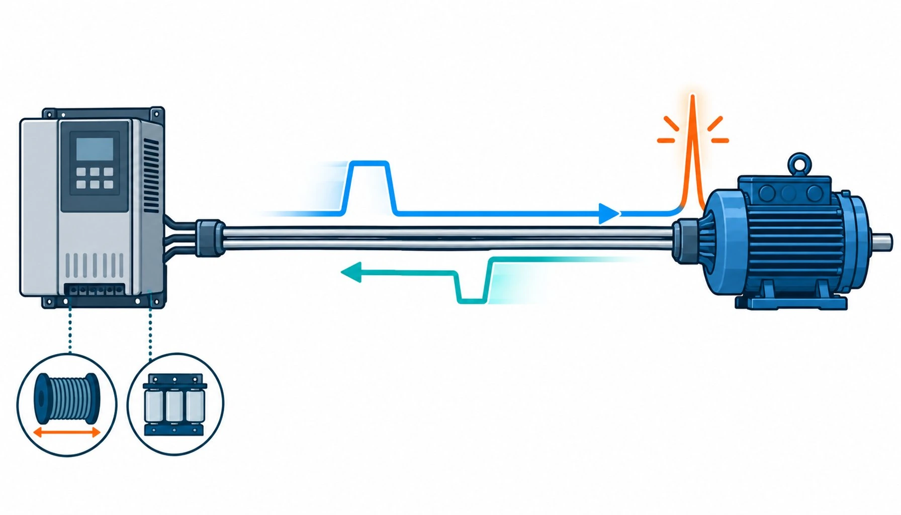
Quick Answer: Servo motor cable is a transmission line problem: drive switching edges reflect along the cable, voltage doubling stresses insulation at the motor, and the rules for length, shielding and termination all exist to manage that reflection.
Most cable selection is about surviving the environment. Servo motor cable selection is also about surviving the electronics at its ends, because the drive at one end switches hundreds of volts in tens of nanoseconds, and the cable between drive and motor behaves less like a wire and more like a transmission line with opinions. Get the design right and the power stage is silent and stable. Get it wrong and the failures are distinctive: motor insulation that ages years in months, bearing currents that pit races, drive faults that trace to voltage reflections nobody measured. This guide explains the electrical phenomena behind the rules, why cable length limits exist and what actually constrains them, and the shielding and grounding practice that closes the loop.
Introduction
The modern servo drive is a switching power stage: a DC bus chopped by insulated-gate transistors into the pulse-width modulation that synthesizes the motor’s three phases, the switching technology that also shapes the choice between drives and soft starters. The chopping is fast, deliberately fast, because faster edges mean lower switching losses and better control bandwidth. But the cable between the drive and the motor does not know about intentions; it knows about physics. A voltage edge traveling down the cable arrives at the motor, meets an impedance mismatch, and part of it reflects back. The reflected edge combines with incoming edges, and at the motor terminal the voltage can momentarily approach twice the DC bus level. The faster the edge and the longer the cable, the more the reflections stack.
Every servo motor cable rule a buyer will meet, length limits, dv/dt ratings, reactor recommendations, shielding mandates, is a management strategy for this one phenomenon. Understanding it turns a list of mysterious requirements into a coherent design, and this guide is that explanation in plain language.
What dv/dt Actually Does Inside the Cable
dv/dt is the rate of voltage change at a switching edge, volts per microsecond. Modern drives produce edges in the several-seconds-of-microseconds class, and the edge is what the cable experiences at every pulse. Three consequences follow. First, the edge sees the cable as a transmission line: characteristic impedance, propagation delay and reflections become real engineering quantities whenever the cable is long relative to the edge rise time, which at nanosecond edges means even modest runs of twenty or thirty meters qualify. Second, the reflected wave superimposes at the motor terminals, producing the overvoltage that stresses the motor’s insulation system, particularly the first turns of the winding where the stress concentrates. Third, the edge couples capacitively into everything near the conductors: the shield, the other cores, the encoder pairs sharing the harness, and the motor’s frame through stray capacitance, which is the origin of the bearing-current story.
Motor insulation systems carry dv/dt ratings for exactly this reason, and cable construction interacts with the ratings through its characteristic impedance and its length. The system is designable, but only when all three elements, drive, cable and motor, are treated as one circuit rather than three purchases.
Why Cable Length Limits Exist, and What Sets Them
Drive manufacturers publish maximum motor cable lengths, and the numbers puzzle buyers until the mechanism is clear. The limit is not resistance or voltage drop, those are trivial at servo power levels over typical lengths. The limit is reflection: beyond a certain length for a given edge speed, the reflected overvoltage at the motor exceeds what the insulation system tolerates. Faster edges mean shorter allowable cables, which is why the newest, most efficient drives sometimes have the strictest limits, and why output reactors, filters or dv/dt chokes, which slow the edge before it reaches the cable, extend the allowable length.
The buyer’s practical version of this rule: treat the drive’s length limit as a system boundary, and when the machine’s geometry demands more cable than the limit allows, solve it with the approved engineering tools rather than by hoping. The tools and their scope are compared below, because each buys back length differently.
| Phenomenon | Where it strikes | Design response | Evidence to demand |
|---|---|---|---|
| Reflected wave overvoltage | Motor terminals, first winding turns | Respect drive length limits; edge filters or reactors on long runs | Length limit statement matched to the drive family; insulation dv/dt rating |
| High dv/dt stress | Cable insulation, terminations | Cross-linked, void-free insulation systems | Partial discharge test data on the finished cable |
| Common-mode currents | Bearings, encoder, plant ground | Low-impedance braid shield, 360-degree both ends, designed return path | Shield construction data and termination system specification |
| Radiated emission | Nearby signal cable and equipment | Braid coverage, separation discipline in the carrier | Shield coverage figures; EMC test references where claimed |
| Bearing currents | Motor bearings | Shield return path plus motor-side measures where drives specify them | System-level guidance from the drive maker, followed in the harness |
Shielding and Grounding: Closing the Loop
The shield on a servo motor cable has two jobs that static cable never asks of it. It contains the radiated field of the switching edges, protecting everything nearby. And it provides the designed return path for the common-mode currents that the switching creates, keeping them off the bearings, the encoder and the rest of the plant. Both jobs demand low impedance from the shield, which means dense braid construction, 360-degree termination at both the drive and motor ends, and a grounding architecture that treats the shield as part of the power circuit, because at switching frequencies it is.
The moving-machine version of these rules, braid fatigue, termination degradation and the verification practices that catch both, follows the grounding discipline of control cabinet construction extended into the moving part of the machine, and the feedback elements sharing the harness deserve the separation discipline compared in the guide to control versus instrumentation cable. For the insulation materials inside the power cores, the cross-linked compounds that tolerate switching stress share their chemistry with the static-cable grades compared in the guide to XLPE insulation.
Construction Choices That Match the Electrical Duty
Inside the jacket, servo motor cable is shaped by the switching environment. Insulation must tolerate the dv/dt stress without partial-discharge aging, which favors cross-linked compounds and clean, void-free extrusion. The three phase cores are laid symmetrically, and the symmetric geometry matters electrically, not just mechanically: balanced impedance between phases keeps the switching stress distributed. Shields are braid, sized for the current they will carry at switching frequency, and hybrid constructions that add encoder pairs or brake cores separate the noisy and the sensitive with individual shields and physical spacing.
The table below summarizes the electrical phenomena, the design responses and the evidence a buyer should demand, in the order the phenomena occur along the cable.
| Tool | How it works | Buys | Watch-outs |
|---|---|---|---|
| Output reactor | Inductance slows the edge reaching the cable | Moderate length extension, reduced dv/dt at motor | Added voltage drop, heat, cabinet space |
| dv/dt filter | Shaped impedance targets the edge rate specifically | Longer runs, motor insulation protection | Sizing must match the drive family; follow maker guidance |
| Sine filter | Reconstructs a near-sinusoidal output | Longest effective runs, lowest motor stress | Cost, size, thermal load; usually reserved for hard cases |
| Softer drive edge setting | Slower switching at the source | Free length extension where control bandwidth allows | Higher switching losses; verify drive thermal budget |
| Relocated drive or motor | Shortens the run geometrically | Removes the problem rather than managing it | Machine layout constraints; may move the problem to another axis |
When Cable Rules Are Not the Whole Answer
Honest limits: the cable is the middle of a three-party system, and several servo problems that look like cable problems are not. Bearing currents have motor-side and drive-side mitigation measures that no cable replaces. Motor insulation quality is the motor maker’s discipline; a perfect cable cannot compensate for an insulation system below the drive’s demands. Drive-side settings, edge times, switching frequencies and filter parameters, live in the commissioning engineer’s scope, and the cable specification should reference them rather than pretend to absorb them. And installation realities, a gland that converts the 360-degree termination into a pigtail, a length run past the limit because the cabinet moved in a redesign, defeat the best construction. The cable rules are necessary and specific, and they operate inside a system whose other parts must carry their own weight.
RFQ Checklist: Specifying Servo Motor Cable
Bring the electrical duty to the supplier in specifics:
- Drive family and switching behavior: edge speed class, voltage level, published cable length limit
- Run length drive to motor, and whether filters or reactors are in the plan
- Motion duty of the route: radius, cycles, any twist
- Hybrid content: brake cores, encoder pairs, and their separation requirements
- Evidence required: partial discharge data, shield construction and flex-cycle test with shield monitoring
- Termination system: 360-degree glands or connectors at both ends, matched to the EMC architecture
Conclusion
Servo motor cable is the transmission line between two aggressive electronic systems, and its design rules are the physics of switching edges made practical: respect the length limits that reflections impose, choose insulation that tolerates the edge stress, build the shield as the designed return path, and terminate it at both ends with the low impedance the switching frequencies demand. The rules are coherent once the phenomenon is understood, and the evidence behind them, partial discharge data, shield test data, length limit matching, is checkable like any other engineering claim.
Kexingyu Cable Group (KXYE) builds servo motor cable for the switching environment the drive actually produces, with partial-discharge-tested insulation, flex-engineered shields and hybrid constructions that protect the feedback pairs. Send your drive and motor details through the RFQ page, and we will rate the cable for the edges it will carry.


