Site Generator Cable: Specifying Connections for Temporary Generators on Construction Sites
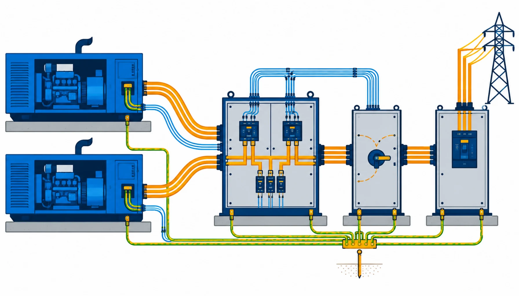
Quick Answer: The cable around a temporary generator covers four jobs: the feeders from sets to boards, the control and pilot cables for paralleling, the ATS changeover links, and the earthing that ties the whole temporary system together. Most site generator problems are connection problems, not set problems. Size the feeder for starting, buy the control cables screened and separated from power, and freeze the generator bay layout before the sets arrive.
Introduction
Generators are the one part of a temporary power system that arrives complete. The cable around them does not, and it is usually ordered last, cut to whatever the bay layout turns out to be, and blamed for every fault the sets are having. A generator bay specified around its cable works differently: the feeders are sized once, the control wiring survives the site, and the changeover actually changes over when the mains fails.
This guide covers the cable side of temporary generation on construction sites: what to size, what to separate, what to standardise, and what to freeze before the sets land on the skids.
The Four Cable Jobs Around a Generator
Power feeders. From each set to the paralleling board or distribution boards, sized on starting behaviour and run length, not just the nameplate.
Control and paralleling cables. The load-sharing, synchronising and monitoring signals between sets and the control panel. These are low voltage, noise sensitive, and the first casualties when power and control share a tray.
ATS and changeover links. The cabling between mains supply, generator and the changeover device. These circuits sit idle for months and have to work in seconds.
Earthing. The earth electrode system, the set earths and the bonding across the temporary installation. Not glamorous, and the reason a generator system passes or fails inspection.
Sizing the Feeders
Generator feeders are short compared with site feeders, which is exactly why they get sized carelessly. Two factors push the other way.
Starting and load steps. Generators are loaded in steps as boards transfer on, and each step is a voltage dip the set recovers from. The feeder must carry the transient without adding a dip of its own, which sizes the conductor larger than the running figure suggests. Give the supplier the step-loading sequence, not just the total kilowatts.
Heat in the bay. Sets radiate; the bay is the warmest cable environment on site, and cable in a bundled tray between two running sets sees it continuously. Ask for the derated ampacity at the bay temperature, and keep feeders out of the radiator exhaust paths wherever the layout allows.
The sizing discipline is the same one that governs battery and DC connections, and our note on battery and inverter cable sizing covers the general method of sizing for short high-current runs.
| Cable job | Duty | What to Specify | Evidence to Demand | Cost and Lead-Time Driver | How It Fails |
|---|---|---|---|---|---|
| Power feeders, set to board | Short runs, high current, step loading, warm bay | Conductor sized for transient dip, high-temperature sheath rating, factory-fitted lugs, lengths to the bay layout | Derated ampacity at bay temperature, conductor resistance records, lug and crimp specification | Copper-heavy and short; the lugs and fitting discipline are the value | Hot lugs, dips at load steps, insulation ageing in the exhaust path |
| Control and paralleling cables | Load sharing and sync signals between sets, noise sensitive | Screened multicore with drain, separation from power runs, core schedule matched to the governor and synchroniser | Screen coverage figures, core schedule, flex and continuity records | Small order line; screening grade and separation decide the outcome | Hunting sets, sync that drifts with pump starts, phantom faults |
| ATS and changeover links | Idle for months, must work in seconds, both sources live | Cable rated for both sources, core schedule matched to the ATS, glands and sealing for outdoor panels | Scheme drawing, continuity records, insulation tests at commissioning | Modest cost; the testing regime is the real deliverable | Changeover that fails after months idle, water in an outdoor panel gland |
| Earthing and bonding | Static duty, safety critical, inspection headline | Earth conductor sizes to the scheme, electrode connections, bonding across boards, accessible test points | Earth loop values, bonding schedule, test records at each reconfiguration | Copper cost is small; the design time is the investment | Inspection failures, floating neutrals, shocks that trace to a missing bond |
Paralleling: Where Control Cable Earns Its Money
Two or more sets running in parallel share load through control signals that measure phase, load and frequency, and the quality of those signals is a cable question as much as a controls question. Power and control in one tray puts every contactor operation into the synchroniser’s inputs, and the symptom is sets that hunt or drop load share for reasons no one can repeat.
The specification is short: screened multicore with a drain, a core schedule matched to the governor and synchroniser actually fitted, and physical separation from the power feeders for the whole run. Where a crossing is unavoidable, cross at right angles and note it on the drawing. The equipment side of synchronising sets is covered in our note on generator synchronisation systems, and the cable is what makes that equipment behave.
ATS and the Mains Interface
The changeover link is the most neglected cable in the bay, because it does nothing until the day it matters. The failures are predictable: water in an outdoor gland, a core schedule that drifted from the ATS’s actual wiring, and terminals that loosened over months of vibration. Specify outdoor-rated glands, match the core schedule to the changeover device by drawing rather than by assumption, and add the ATS links to the monthly test so the changeover proves itself with a load on it. The connections that fail and the fixes are covered in our note on generator ATS cable connections.
The Board Interface and Beyond
From the generator board downstream, the temporary system is ordinary site distribution, and the same heavy rubber connecting cable standard covers it; our note on heavy rubber connecting cable covers the standard constructions. Where the site’s load has grown past what sets and cables carry economically, the answer is a closer source: the skid-mounted transformer and substation options in our note on prefabricated substations change the generator bay from a power station back into a standby role.
Earthing the Temporary System
Earthing is the least negotiable part of the generator bay and the part most often improvised. The scheme is small: electrodes at the bay, earth conductors sized to the design, bonding across every board and metallic enclosure, and accessible test points so the next inspection does not dig anything up.
Design it once for the site. A bonding schedule drawn for the actual board positions, updated at each reconfiguration, survives the whole build. Patching earths per inspection costs more than the design every time, and inspectors can tell the difference at a glance.
Connect it properly. Earth connections fail by loosening and corrosion, not by design. Use the same gland and lug discipline as the power circuits, protect the electrode connections from mechanical damage, and photograph the as-built scheme at commissioning so the records match the ground.
Test it on a schedule. Earth loop and bonding tests belong in the monthly generator test, with the values written on the schedule. Rising loop values between tests are how a degrading connection announces itself before it becomes a finding.
Rental Fleets and Standardisation
Where the fleet is rented, the bay is rebuilt on every project, and the cable is the part that carries the learning. A fleet that standardises feeder lengths, lug sizes, control cable types and the core schedule between boards rebuilds its bays in hours instead of days, and the spares stock actually fits the machines that break.
The procurement move is to buy the standard, not the project: specify the standard cable package once, hold it, and consume it across jobs. Units get their connections rebuilt with tested, familiar cable, and crews stop inventing a bay from scratch each mobilisation. The economics of holding that stock against copper movement are the same as any working copper position, and they reward a supplier who quotes metal on a basis rather than resetting at every call-off.
What to Freeze Before the Sets Arrive
| Decision | What to State | Evidence to Attach | Cost of Leaving It Open |
|---|---|---|---|
| Bay layout | Set positions, board positions, cable routes and crossings | A layout drawing with the routes drawn | Feeders cut to a layout that changed on delivery day |
| Feeder sizing basis | Step-loading sequence, bay temperature, run lengths | Derated ampacity calculation per feeder | Dips at every load step and hot lugs |
| Control separation | Screened multicore, core schedule, separation from power | Core schedule matched to the fitted controls | Sets that hunt and a fault nobody can repeat |
| ATS links | Core schedule by drawing, outdoor glands, test regime | Scheme drawing and commissioning test records | A changeover that fails on the day it is needed |
| Earthing scheme | Electrodes, bonding across boards, test points | Earth loop values and bonding schedule | An inspection failure at the worst phase of the build |
| Spares and standardisation | Spare feeder lengths, spare control cable, standard lugs | A spares list tied to the bay drawing | A set offline for a lug while the board waits |
Lead Time and Cost Structure
Generator bay cable is a fast line. Feeders, control cable and earthing stock are available in days, and factory-fitted lugs on standard sizes add little. The sequencing that matters is against delivery of the sets: the bay cable, glands and earthing land with the site establishment, so the sets energise boards the day they arrive rather than a week later.
On cost, the copper in short feeders is modest, and the money that matters is in doing the sizing and separation work once. Rental fleets renew connections constantly, which makes standardising lug sizes, feeder lengths and control cable across the fleet a genuine saving; our note on copper price and cable procurement covers how the metal content behaves for buyers holding that kind of stock.
Incoming Inspection and Commissioning
At delivery. Check feeder lengths against the bay drawing, verify lug sizes against the set terminals and board glands, and run continuity and insulation on every feeder and control cable before installation.
At commissioning. Test the earth loop and bonding, prove the ATS under load, and record the synchronising behaviour with the sets loaded. The records go with the boards, because the bay will be reconfigured and the next crew needs the baseline. Where the client’s engineer witnesses the works, our note on third party cable inspection covers the evidence trail.
When a Generator Cable Specification Is Not the Answer
When the sets themselves are the problem. Hunting that follows a fuel or governor fault is not cured by re-cabling the controls. Diagnose the set first; the cable change is only real when it stops the same fault in a different set.
When the load has outgrown the bay. Adding set after set to feed a load that a transformer would serve better is the expensive path. Re-derive the architecture, and the cable order shrinks with it.
When earthing is being patched per inspection. Recurrent earthing findings mean the scheme was never designed for the site as built. A bonding design for the current layout is cheaper than the third round of remedials.
When the changeover has never been tested under load. No cable specification protects an ATS that fails its first real transfer. The monthly test is the specification.
RFQ Checklist
- Bay layout with set and board positions, and the cable routes drawn
- Feeder lengths with the step-loading sequence and bay temperature
- Derated ampacity calculation at bay temperature, per feeder
- Factory-fitted lugs matched to the set terminals and board glands
- Control core schedule matched to the fitted governor and synchroniser
- Screening and separation requirements for control runs
- ATS core schedule by drawing, with outdoor gland specification
- Earthing scheme with electrode, bonding and test point schedule
- Commissioning tests: earth loop, ATS under load, synchronising loaded
- Spares list tied to the bay drawing, and the copper basis with its window
Conclusion
Generator bay cable is bought well when the layout, the sizing basis and the control separation are frozen before the sets arrive. Size feeders for load steps, screen and separate the paralleling signals, test the changeover under load, and the temporary plant behaves like installed plant. Test the earth and the changeover monthly, because those are the two systems that have to work on the day nothing else does.
Kexingyu Cable Group (KXYE) has manufactured cable in Quanzhou since 1996, including the feeder, screened control and earthing constructions temporary generation runs on, with factory-fitted lugs and the test records commissioning needs. Send us the bay layout and load sequence, and we will come back with the cable schedule, the calculations and a delivery plan against the set delivery dates. The fastest route is a request for quotation.