
Solar-Plus-Storage: How the Two Systems Work Together
Learn how PV, batteries, inverters, PCS, BMS, EMS, meters, and switching equipment coordinate in AC- and DC-coupled commercial systems.
Why Solar and Storage Are Paired
Solar generation follows irradiance, while a facility’s electrical demand follows production, occupancy, weather, and operating schedules. Their peaks rarely align perfectly. A battery energy storage system can move some solar energy to a later time, limit grid import, control export, or preserve energy for outages.
Storage does not create additional solar energy. Every charge-discharge path has losses, the battery has finite power and usable capacity, and its availability depends on state of charge. The value comes from changing when and how energy is used, not from increasing the PV array’s annual production.
The right design begins with a time-series model of solar output, site load, tariffs, export limits, outages, and operating priorities. Equipment architecture should follow those requirements.
The Core Equipment in a Solar-Plus-Storage System
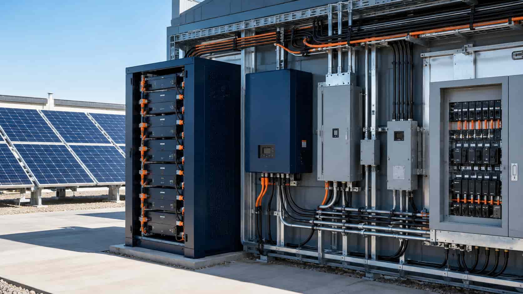
The PV array produces DC electricity. A solar inverter converts it to AC in a conventional grid-connected plant. A battery stores DC energy, while a bidirectional PCS or hybrid inverter charges and discharges it.
The BMS monitors the battery and publishes safe charge and discharge limits. The EMS uses load, solar forecasts, tariffs, meter data, SOC, and reserve requirements to request operating modes and power. Our BMS-versus-EMS guide explains this authority hierarchy.
Switchgear, transformers, meters, protection relays, export controllers, transfer equipment, grounding, auxiliaries, and communications complete the system. A solar array and battery placed on the same site are not fully integrated until these interfaces are engineered and tested.
AC-Coupled Solar-Plus-Storage
In an AC-coupled system, the PV inverter and battery PCS are separate. Each connects to a common AC bus, directly or through transformers and switchgear. Solar serves AC loads or exports through the PV inverter; charging the battery from solar normally involves conversion from PV DC to AC and then AC to battery DC.
AC coupling is often attractive for adding storage to an existing solar plant because the original PV DC design and inverter can remain largely intact. It also allows the PV and battery power ratings, suppliers, maintenance, and replacement schedules to be more independent.
Retrofit does not mean approval-free. Adding a bidirectional resource can change fault levels, transformer loading, protection, export behavior, metering, utility studies, and the interconnection agreement. The site may also need a new EMS or plant controller to coordinate the two inverter systems.
DC-Coupled Solar-Plus-Storage
In a DC-coupled design, the PV and battery share a DC-side architecture before a common grid-facing inverter. Depending on scale, this may use a hybrid inverter or dedicated DC-DC converters that regulate the PV and battery against a shared DC bus.
Solar energy can charge the battery without first passing through a PV inverter and then a battery PCS. This can reduce conversion stages for that specific path and can capture some PV energy that would otherwise be clipped when the DC array output exceeds the shared inverter’s AC limit.
The trade-off is tighter integration. PV voltage windows, MPPT architecture, battery voltage, DC protection, grounding, fault detection, controls, inverter capacity, warranty boundaries, and future replacement must all be compatible. A shared inverter can also become a common capacity constraint or outage point.
AC Coupling vs DC Coupling: Use the Correct Efficiency Boundary
It is misleading to declare one architecture universally more efficient. Compare the energy path that matters. Direct daytime PV-to-load energy can have a short path in a conventional AC system. PV-to-battery-to-AC energy in an AC-coupled system usually crosses additional conversions, while a DC-coupled system can charge on the DC side.
Real annual performance also includes inverter loading, DC-DC efficiency, battery losses, transformer losses, wiring, clipping recovery, standby consumption, cooling, curtailment, degradation, and dispatch. Request an hourly or sub-hourly simulation using manufacturer efficiency maps rather than one peak-efficiency figure.
How Energy Flows During a Typical Day
In the morning, solar output rises and reduces grid import. Whether the battery charges immediately depends on the forecast, tariff, SOC target, and need to preserve charging headroom for midday surplus.
Around midday, solar may exceed the site load or export limit. The EMS can direct surplus to the battery within BMS and converter limits. In DC-coupled plants, storage may also absorb PV energy above the shared inverter’s instantaneous AC capability when the DC architecture permits.
In the late afternoon or evening, the battery can discharge to reduce grid import, avoid an on-peak tariff, limit billed demand, or meet a contracted dispatch. It should not discharge merely because solar has fallen if later peaks or backup reserve are more valuable.
Overnight, the system may remain at reserve SOC, charge from the grid when permitted and economical, or prepare for the next day. Tariff rules, grid services, weather forecast, and battery warranty influence the schedule.
Who Decides Where the Energy Goes?
The EMS selects the economic or operational objective, but it does not override hard equipment limits. It sends setpoints to the hybrid inverter, PCS, or plant controller. The BMS can reduce permissible battery power, and each inverter can constrain a command because of voltage, temperature, current, grid, or protection conditions.
A point-of-connection meter provides feedback for import, export, or demand control. Separate PV, battery, and load meters support performance verification. Define sign conventions, update rates, time synchronization, command priority, communications-loss behavior, and data ownership.
When the EMS is cloud-based, essential local controls must continue safely without internet access. Export limiting and protection typically need deterministic local behavior.
Export Limiting and Interconnection Capacity
A battery can charge during high PV output and reduce export, but it is not a guaranteed export-control device unless the controls, meter, response, SOC management, and fail-safe behavior are designed for that purpose. Once the battery is full or unavailable, the PV system must curtail or the site can exceed its limit.
A shared point-of-interconnection rating does not automatically allow the PV and battery nameplate ratings to be added behind it. Utilities may evaluate maximum export, charging import, operating modes, relay settings, communications, and simultaneous failure cases.
For multinational projects, verify exact inverter and PCS grid-code evidence by country and firmware, as described in our inverter grid-code compliance guide.
Backup Power: Why Ordinary Grid-Tied Solar Shuts Down
Most standard grid-following solar inverters stop energizing the grid during an outage as part of anti-islanding protection. Adding a battery does not automatically change that behavior.
Backup operation requires an intentional island: suitable isolation or transfer equipment, a grid-forming source, island-mode protection, neutral and grounding design, black-start sequence, critical-load distribution, load shedding, and controls that balance generation and demand.
The battery or another grid-forming resource normally establishes voltage and frequency. The PV inverter must be approved to operate within that island and respond to frequency or power commands when generation exceeds load and available charging capacity. Motor starting, transformer inrush, fault current, transfer time, and restart sequence must be studied.
Sizing PV and Storage Together
Size the PV array from site energy goals, available area, irradiance, losses, export rules, and interconnection capacity. Size PCS power from the required charge and discharge rate, peak shaving, backup load, or grid service. Size battery energy from the time-series energy requirement, SOC window, efficiency, reserve, temperature, and degradation.
For peak shaving, integrate the load above the demand target rather than multiplying one maximum by a guessed duration. Our peak-shaving BESS sizing guide provides a practical calculation method.
Simulate multiple years or representative weather and load scenarios. Include consecutive cloudy days, seasonal load, PV degradation, battery degradation, maintenance outages, future expansion, and tariff sensitivity.
Clipping, Curtailment, and Solar Charging
Clipping occurs when available PV DC power exceeds the inverter’s usable AC power. DC-coupled storage may capture a portion if battery charge power, SOC headroom, DC-DC capacity, voltage, and controls permit. It cannot capture clipped energy when the battery is full, constrained, or reserved for another service.
Curtailment can also result from export limits, negative prices, grid commands, voltage conditions, or plant constraints. AC-coupled storage may absorb energy that would otherwise be curtailed if the control architecture and interconnection agreement permit charging at that moment.
Model recoverable energy rather than assuming every clipped or curtailed kWh becomes battery revenue.
Retrofit Considerations
For an existing PV site, document inverter model and warranty, AC and DC capacities, transformer and switchgear loading, protection settings, point-of-connection limits, meter arrangement, SCADA interfaces, space, cable routes, fault levels, and historical clipping or curtailment.
AC coupling often minimizes changes to the PV DC system. DC-side retrofit can be attractive in specific designs but may require new compatible conversion equipment, DC reconfiguration, shutdowns, and warranty review.
Check whether incentives, contracts, renewable-energy accounting, or charging-source rules require the battery to track solar charging. Metering and controls must support any claim.
AC vs DC Coupling Comparison
The table below summarizes common differences, not universal outcomes. Product topology, site voltage, project scale, grid rules, retrofit condition, and supplier scope can reverse apparent advantages. Compare complete designs using the same performance and cost boundary.
| Decision factor | AC-coupled | DC-coupled |
|---|---|---|
| Architecture | Separate PV inverter and bidirectional battery PCS share an AC bus. | PV and battery share a DC-side architecture and grid-facing inverter. |
| Solar-to-battery path | Normally PV DC → AC → battery DC. | PV DC can charge the battery through the shared DC architecture. |
| Retrofit suitability | Often easier for an existing PV plant, subject to electrical and utility review. | Usually more integrated and commonly favored for purpose-designed new plants. |
| Clipping recovery | Can absorb otherwise curtailed AC energy when control and interconnection permit. | May capture PV output above the shared inverter AC limit when battery headroom exists. |
| Equipment independence | PV inverter and battery PCS can be sized, serviced and replaced more independently. | PV, battery, DC-DC conversion and shared inverter compatibility are more tightly linked. |
| Conversion efficiency | Additional conversions normally occur for PV-to-battery-to-load energy. | Can reduce conversion stages for direct solar charging; annual outcome remains design-specific. |
| Single-point constraints | Separate converters can limit common-mode outages but add equipment. | Shared inverter capacity or outage can affect both PV and battery delivery. |
| Best evaluation | Use hourly or sub-hourly simulation with identical load, weather, tariff, export, efficiency, degradation, auxiliary and availability assumptions. | |
Directional comparison only. Actual topology, performance, cost and approval requirements depend on project scale, voltage, equipment design, grid rules, retrofit conditions and supplier scope.
Commissioning Tests
Verify meter polarity and scaling, solar and battery setpoints, BMS limits, SOC calibration, import and export controls, PV curtailment, maximum charging, maximum discharge, transformer and switchgear operation, alarms, communications loss, and restart.
If backup is included, test utility loss, transfer, grid formation, PV reconnection within the island, load steps, motor starting, low-SOC behavior, solar surplus, load shedding, emergency stop, and return to grid.
Confirm reporting reconciles PV production, battery charge and discharge, grid import and export, site load, losses, and auxiliaries. Energy balances are a powerful way to detect mapping and metering errors.
Questions to Ask Suppliers
Is the proposed system AC-coupled or DC-coupled, and which equipment and conversion paths are included?
What are the PV, battery, inverter, PCS, transformer, point-of-connection, charge, discharge, and usable-energy ratings at defined conditions?
Which energy-flow simulation, efficiency maps, clipping assumptions, degradation, auxiliaries, and tariff inputs support the proposal?
Can the system operate during an outage, and which equipment provides isolation, grid formation, black start, protection and load shedding?
How are PV, battery, EMS, meters, SCADA, and utility interfaces integrated, and what happens when communications fail?
Which certifications, grid approvals, warranties, software licenses, and service responsibilities apply to the exact configuration?
Where Kexingyu Power Fits In
Kexingyu Power can discuss solar inverters, hybrid inverters, PCS, batteries, BMS, EMS, switchgear, transformers, and integration for new or retrofit solar-plus-storage projects. The final architecture must be confirmed against the load, solar resource, tariff, site electrical system, grid rules, backup objective, and local approvals.
Provide interval load and PV data, single-line diagram, existing equipment details, target power and duration, export limit, grid voltage, outage requirements, communications scope, installation environment, standards, and future expansion plan.
Final Takeaway
Solar produces energy; storage changes when that energy is available. AC coupling offers modularity and often simpler retrofit, while DC coupling can reduce conversion stages for solar charging and recover some clipped energy. Neither architecture is always superior.
Choose using time-series performance, total installed cost, approval risk, serviceability, backup requirements, and lifecycle flexibility. Then test every operating mode at the actual point of connection.
Frequently Asked Questions
Practical questions about solar-plus-storage architecture.
It is a coordinated system combining photovoltaic generation with battery storage, power conversion, controls, metering and electrical equipment so solar energy can be shifted, curtailed, exported, reserved or used during approved backup operation.
AC coupling uses separate PV and battery inverters connected to an AC bus. DC coupling connects PV and batteries through a shared DC-side architecture before the grid-facing inverter.
No. It can reduce conversion stages for solar-to-battery energy, but annual performance also depends on inverter loading, DC-DC conversion, transformers, auxiliaries, clipping, dispatch, curtailment and degradation.
It is often simpler because the original PV DC system can remain intact. The retrofit can still require new protection, metering, transformer capacity, export control, utility studies and interconnection approval.
Only when the system is designed for intentional islanding. It needs isolation, a grid-forming source, island-mode protection, critical-load distribution and controls that keep solar generation balanced with load and battery capability.
No. Recovery is limited by battery SOC headroom, charge power, DC or AC conversion capacity, voltage conditions, controls, interconnection rules and competing reserve requirements.
Yes, but the services compete for battery SOC and converter power. The EMS must prioritize them, and the financial model must avoid counting the same capacity as fully available for conflicting services.
Recent Posts
Switchgear Lead Times in 2026: A Buyer’s Planning Guide
Switchgear Lead Times in 2026: A Buyer’s Planning Guide Realistic timelines vary significantly by voltage class and type — here’s how to plan procurement without
What Is BESS? A Guide to Battery Energy Storage Systems for C&I Buyers
What Is BESS? A Guide to Battery Energy Storage Systems for C&I Buyers A clear explainer on what BESS systems actually are, how the pieces
Switchgear vs Transformer Lead Times: What EPC Contractors Need to Know
Switchgear vs Transformer Lead Times: What EPC Contractors Need to Know A practical breakdown of why these two equipment categories behave differently in procurement, and