Transformer Noise and Vibration: Causes and Mitigation
What makes a transformer hum, when that sound is a warning rather than a byproduct, and which design and site measures actually reduce it
Introduction
Every energized transformer hums. Most of the time nobody notices—until the new unit lands next to an office block, a residential wall or a data hall, and suddenly the sound level becomes a contractual issue. Among all the disputes we see at site acceptance, noise is one of the most frequent: the buyer hears something different from the factory test report, the vendor insists the machine is compliant, and both are sometimes right.
The reason for that confusion is simple. Transformer noise is not one phenomenon but several, and it is measured in more than one way. It is also one of the few parameters you can buy directly: like losses or impedance, the sound level can be specified, guaranteed and tested—every step of reduction simply has a price and a size. Buyers who understand where the sound comes from can spend that money where it works; buyers who do not usually end up paying for measures that target the wrong cause.
This guide walks through the physics behind the hum, the five causes that account for nearly every noise complaint, how sound levels are measured and guaranteed, and which design and site measures genuinely reduce transformer noise and vibration—and when they do not. For the wider product context, start from our transformer and substation range, then come back here for the acoustic detail.
What Transformer Noise Actually Is
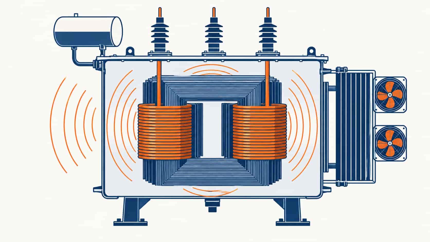
The dominant source sits in the core. Transformer core steel is magnetostrictive: as the magnetic flux alternates, the laminations expand and contract by a few microns, twice in every cycle. A transformer on a 50 Hz system therefore produces a fundamental tone at 100 Hz; on 60 Hz systems, 120 Hz. Because magnetostriction is not perfectly linear, harmonics of that frequency are generated as well, which is why the sound is perceived as a hum rather than a pure tone. The tank and radiators act as sounding boards, radiating the core’s vibration into the surrounding air.
On top of that tonal base sit several broadband sources. Cooling fans dominate on forced-cooled units, and oil pumps contribute their own signature. Winding vibration from load currents adds a load-dependent component, and modern loads—variable frequency drives, rectifiers, UPS systems rich in harmonics—push the magnetostrictive response at frequencies well above the fundamental. DC magnetization, whether from geomagnetic currents or rectifier leakage, skews the flux asymmetrically and raises the noise audibly.
All of this is measured and standardized. IEC 60076-10 defines how sound levels are determined for transformers and reactors, and the same document underlies the noise figures that manufacturers guarantee. That matters for buyers: a sound figure without a measurement basis—a sound pressure or a sound power level, at which cooling stage, under which conditions—is not a specification, it is a suggestion.
The Five Main Causes of Transformer Noise and Vibration
Almost every noise complaint traces back to one of five causes. The first two are design-bound and priced into the unit; the middle ones depend on the duty the transformer actually sees; the last is the one most often misdiagnosed, because it originates on site rather than in the factory.
Cause 1: Magnetostriction in the Core
This is the irreducible hum—the physical signature of an alternating flux in steel. Its level is fixed at the design stage by two choices: the core material and, above all, the working induction. Reducing the flux density from around 1.7 T to 1.6 T lowers the magnetostrictive strain and therefore the sound level by several decibels, at the cost of a larger core, more steel and a heavier, more expensive unit. Step-lap joint construction and better lamination quality further reduce the noise radiated from the joints. No site measure removes this component; it can only be specified lower at purchase.
Cause 2: Core Joints, Air Gaps and Clamping
Where the design intent is compromised in manufacturing or transport, the hum grows. Gaps at the interlayer joints, relaxed clamping pressure after transport, or laminations that have shifted let the core vibrate more freely, converting electrical physics into audible mechanical noise. This is why a unit that tested quietly in the factory can arrive noticeably louder: the core has been handled, and the joints no longer close as they did on the test floor. A sound level re-check at no-load, compared against the factory report, is the fastest way to detect it.
Cause 3: Cooling Fans and Pumps
On forced-cooled power transformers the fans often become the dominant source, adding a broadband roar on top of the tonal hum. Fan noise depends on blade design, tip speed and how many cooling stages are running—ONAN operation may be nearly silent while ONAF transforms the acoustic picture. Pumps add their own tone. Because fan noise is broadband rather than tonal, it annoys differently and is often easier to treat: low-noise blades, smaller faster fans replaced by larger slower ones, variable-speed control that runs fans only as thermal conditions demand, or simply orienting coolers away from the nearest receiver.
Cause 4: Load Currents and Harmonics
Contrary to a widespread assumption, load per se changes little: the classic hum is driven by voltage, present at no-load. What load does contribute is winding vibration from the load current’s electromagnetic forces—usually a minor term at rated sinusoidal current. The exception is harmonic-rich current. Harmonics excite the core at multiples of the fundamental frequency, raising the sound level noticeably on installations feeding drives, rectifiers and UPS systems. If the hum of a unit grows when the production line or the data hall ramps up, that is the signature. The remedy lies in the electrical design—derating, K-factor awareness or filtering—not in acoustic treatment of the tank.
Cause 5: Loose Parts, Resonance and Installation Shortcuts
The most misdiagnosed cause of all: the transformer is fine, but something around it is not. Loose tank covers and shield panels rattle; rigidly connected cable boxes or pipework conduct tank vibration into building structures; a plinth that resonates at 100 Hz turns the whole foundation into a loudspeaker. Transport can loosen what the factory torqued tight. This category explains the classic complaint pattern—a unit that hums louder than its test report, or whose noise is heard in an office two floors above. It is also the cheapest to fix: fasteners, shims, flexible connections and anti-vibration mounts resolve what enclosures and barriers never will.
Use the matrix below to read a noise problem before escalating it:
| What You Observe | Likely Cause | How to Confirm | Typical Fix |
|---|---|---|---|
| Steady 100/120 Hz hum, present even at no-load | Magnetostriction in the core | Compare the factory sound test with a like-for-like site reading per IEC 60076-10 | Specify lower induction or a step-lap core on replacement; barriers and distance on site |
| Hum rises when harmonics-rich load ramps up | Load and harmonic currents exciting the core | Correlate sound level with load; measure current THD | Derate or design for the harmonic spectrum; add filtering upstream |
| Clearly louder than the factory test report after energizing | Transport damage or relaxed core clamping | Repeat the no-load sound check; inspect core clamping and tank bolts | Re-torque and re-shim under warranty before accepting the unit |
| Roar that appears only when fans start | Cooling fans or oil pumps | Compare ONAN and ONAF operation at the same voltage | Low-noise or variable-speed fans; orient coolers away from receivers |
| Rattle at covers, radiators or pipework | Loose panels; rigid pipe and cable-box connections | Hand survey or vibration scan around the tank and its connections | Torque fasteners; fit flexible connections and anti-vibration mounts |
| Complaints even though readings look normal | Measurement basis or site reflection mismatch | Check whether quoted values are sound pressure or power; account for reflective walls | Agree one measurement basis; treat the acoustic environment |
How Transformer Noise Is Measured and Guaranteed
IEC 60076-10 is the reference for determining sound levels of power transformers and reactors. The standard defines two quantities that buyers routinely confuse. Sound pressure level (Lp, in dB(A)) is what a microphone at a specified distance hears—typically 0.3 m for small units and 2 m for larger ones. Sound power level (Lw) is the total acoustic energy the machine emits, calculated from the pressure measurements over a defined surface. A transformer quoted at 65 dB(A) sound power is not the same animal as one quoted at 65 dB(A) sound pressure; the difference is on the order of 15 to 20 dB for medium units. Every comparison between quotations, and every dispute at site acceptance, starts with confirming the basis.
Measurement conditions matter just as much. The standard measures at no-load and rated voltage, on a sinusoidal supply, at defined microphone positions on a contour around the unit—so the classic hum is what the factory figure represents. Fan noise is either measured at each cooling stage or calculated separately, which is why a guarantee should name the cooling stage it covers. Site measurements, in contrast, are affected by reflective surfaces, nearby equipment and background noise, which is why a site reading that differs from the factory report is not automatically a defect—sometimes it is acoustics of the yard.
For buyers, three practical rules follow. First, require the sound level to be guaranteed in the contract, with the basis (pressure or power), the measurement standard and edition, and the cooling stage all named. Second, accept a tolerance—acoustic guarantees are typically given with the same order of tolerance as other routine parameters, and zero-tolerance sound promises invite disputes. Third, if a site noise limit governs the project, ask for a sound study of the proposed layout before purchase rather than a louder argument after installation.
Design Measures: Buying a Quieter Transformer
The most effective decibel is the one never radiated. At the design stage, the levers are clear. Lowering the working induction by roughly 0.1 T brings several decibels of reduction and is priced in core steel and dimensions—this is the single biggest design choice behind the hum. Step-lap joints and higher-quality domain-controlled laminations reduce the joint contribution. Acoustic tank design—stiffer tanks, damping treatments, resilient mounting of radiators and cable boxes internally—prevents the core’s vibration from reaching structures that radiate efficiently.
Cooling deserves equal attention on larger units. Fan choice spans from standard industrial blades to low-noise profiles, and variable-speed drives let the cooling follow the thermal load instead of running flat out—on many installations this removes the dominant noise source for most of the year and saves energy doing it. On dry-type cast-resin units the acoustic profile differs from oil-immersed machines—enclosed IP-rated cases add their own attenuation, and the ventilation path matters; our comparison of oil-immersed and dry-type transformers covers that choice in detail.
The mitigation options and their trade-offs, compared:
| Measure | Where It Applies | Typical Effect | Trade-offs | Best For |
|---|---|---|---|---|
| Lower core induction, step-lap joints | Design stage, new units | Several dB(A) at the source | Larger core; higher price and weight | Units near offices, residences or data halls |
| Low-noise or variable-speed fans | Forced-cooled units | Removes the dominant broadband source; VSD saves energy | Cost and control complexity | Urban substations with night-time limits |
| Acoustic enclosure or lagging | Existing installations, retrofit | Typically 5â15 dB(A) attenuation | Access, ventilation and heat rejection must be engineered | Fixed sites close to noise-sensitive receivers |
| Anti-vibration mounts and flexible connections | Installation and commissioning | Cuts structure-borne transmission into the building | Plinth and connection design required | Indoor transformer rooms, skids, data centers |
| Distance, orientation and barriers | Site layout | About 6 dB per doubling of distance in free field; walls add shadow-zone attenuation | Consumes land; aesthetics | Greenfield projects with layout freedom |
| Clamping and fastener maintenance | Operation and after transport | Restores the factory sound level | Minimal | Aging units and post-transport acceptance |
Site Measures: What Installation Can and Cannot Fix
For an existing unit, the acoustic environment is the main lever. Distance is the cheapest attenuation there is: in free-field conditions, doubling the distance from the source lowers the sound pressure level by about 6 dB, and orienting the quietest faces—those without fans—toward the nearest receiver costs nothing at layout stage. Barriers and acoustic walls work when they break the line of sight and are sized generously relative to the wavelength of the 100/120 Hz fundamental; a low decorative fence will do nothing for a tone that diffracts readily.
Structure-borne vibration is the invisible half of the problem, and the half site measures handle best. A transformer rigidly bolted to a common slab with the building transmits the hum directly into the structure, which re-radiates it in rooms far from the yard. Anti-vibration mounts under the tank, flexible connections on cable boxes, bushings turrets and cooling pipework, and a plinth that is not acoustically coupled to occupied structure address this path. None of it is expensive at construction time; all of it is disruptive as a retrofit. Decide it at the design stage of the installation, not after the first complaint from the office upstairs.
When Quieting Is Not the Answer
There is a point past which buying more silence stops making sense, and it arrives faster than most buyers expect. Each further decibel of factory-guaranteed reduction costs disproportionately—larger cores, heavier tanks, exotic fans—and pushes the unit’s price and dimensions up. Guaranteeing 45 dB(A) when the site limit is 60 dB(A) measured differently is spending money to win an argument nobody is having. Match the specification to the actual constraint, with a margin, and stop there.
Likewise, an acoustic enclosure is the wrong answer to a resonance problem: it wraps a container around a unit that is transmitting its vibration into the structure, and the complaint upstairs survives the investment. Before committing to any mitigation, diagnose—use the matrix above, compare factory and site figures on the same basis, and check the transmission paths. And be wary of the cheapest failure mode of all: buying an enclosure sized for the wrong sound field, or measuring the “improvement” with a method different from the one the guarantee used. Noise projects fail on definitions more often than on physics.
What to Specify in Your RFQ
Sound is contractual only if it is written down precisely. A short list that prevents most disputes:
- Guaranteed sound level with the basis named—sound pressure or sound power, dB(A)—per IEC 60076-10 with edition, at no-load and rated voltage.
- Cooling stage coverage: the level at ONAN and at each forced-cooling stage, since fans change the acoustic picture entirely.
- Tolerance on the acoustic guarantee, agreed before quotation so all offers are comparable.
- Site noise target and, where receivers are close, a sound study of the proposed layout—distance, barriers, reflection—before the order.
- Low-noise design options priced as line items (reduced induction, step-lap core, low-noise or VSD fans, acoustic tank design), so the decibels you need can be weighed against the cost they carry.
- Vibration isolation scope: anti-vibration mounts, flexible connections and their responsibility boundary between transformer and civil works.
- Witnessed sound measurement at the factory test, with the report stating the method, positions and background noise correction.
Most of these points belong in the technical dialogue long before the commercial round. Our checklist for vetting a transformer manufacturer in China covers the supplier-side questions that pair with it, and if the acoustic requirement stems from an oversize unit reacting to a harmonics-rich load, it may be worth revisiting the capacity sizing logic first.
Conclusion
Transformer noise is physics you can purchase. The hum starts in the magnetostriction of the core and grows through joints, cooling equipment, harmonics and installation shortcuts—and each of those five causes responds to a different remedy, from lower induction at the design stage to anti-vibration mounts at the plinth. The diagnosis comes first: the pattern of the sound, compared against the factory test on the same measurement basis, tells you which cause you are treating.
Specify the sound level you actually need, with its basis and tolerance; spend on source reduction where receivers are close; and give the installation its due with distance, barriers and vibration isolation. Do that, and the hum stays where it belongs—in the yard, under the contract limit, and out of your acceptance meetings. When you are ready to put a quiet unit on order, our team at KXY E-Power Group can price the acoustic options alongside the electrical ones.