
Automatic Transfer Switch (ATS) vs Static Transfer Switch (STS): What's the Difference?
Both devices move a load from one power source to another—the difference is whether a few milliseconds of interruption matters to what you are powering
Introduction
Redundant power only counts if the load actually reaches it. Two feeds, a generator and a storage system are all preparation; the transfer device is where preparation becomes protection. Yet “transfer switch” is used loosely across the industry, and the two devices hiding under that label—an Automatic Transfer Switch (ATS) and a Static Transfer Switch (STS)—differ in technology, speed, cost and, most importantly, in where they belong in a power system. Choosing the wrong one does not usually cause an outage; it quietly leaves one in reserve for the day the load turns out to be more sensitive than the specification assumed.
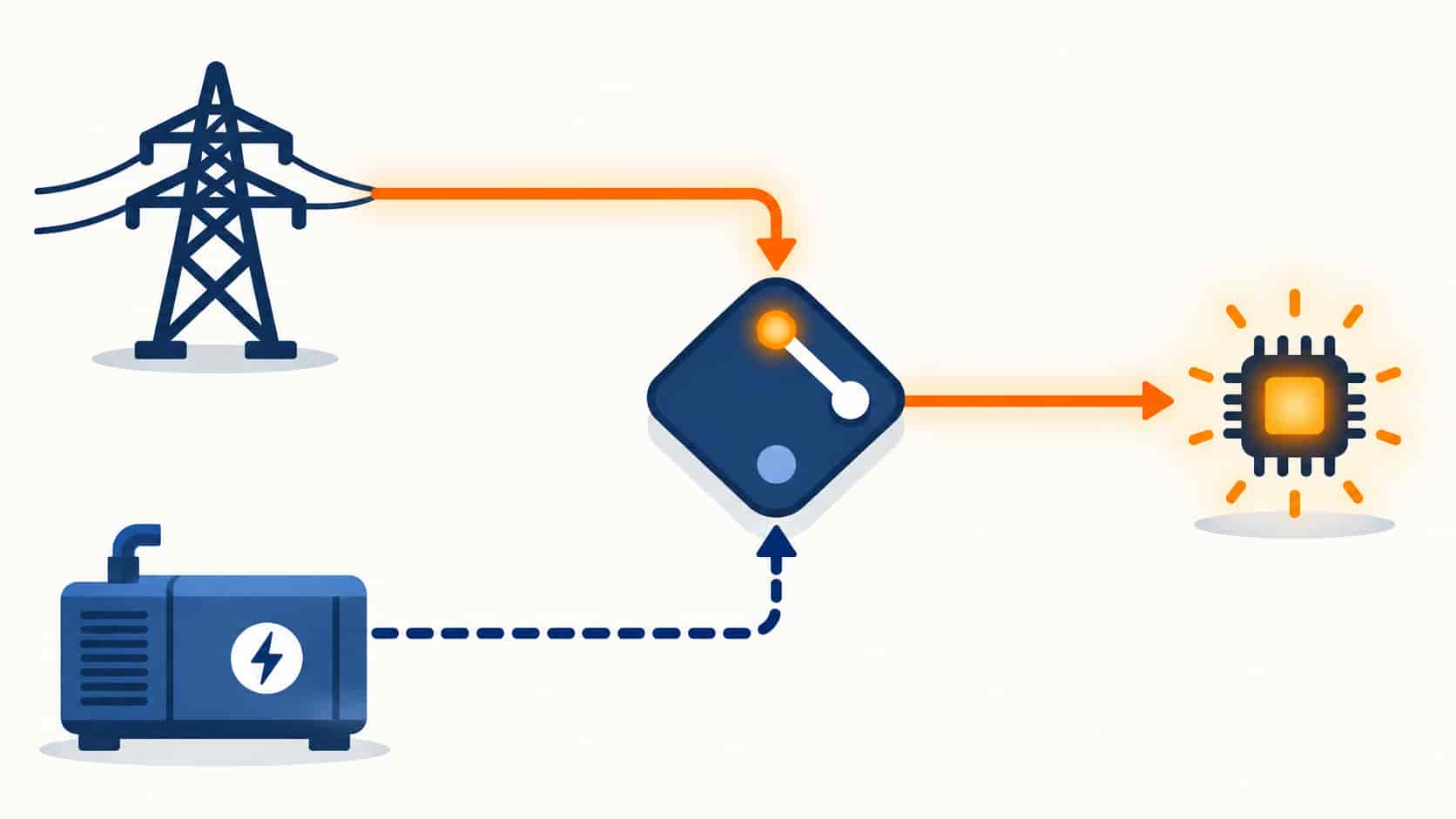
The confusion is understandable. Both watch two sources and move the load when one degrades. But an ATS is an electromechanical machine—contacts physically part and close—while an STS is a power-electronic one, semiconductors conducting the source change with no moving parts and no gap. The hundreds-of-milliseconds versus sub-cycle gap between them is the entire engineering argument, and it maps directly onto the kinds of loads each device serves.
This guide explains how each device works, compares them line by line, locates each in the data center power train, and closes with a selection table and specification checklist. For the wider equipment context, start from our data center power equipment range.
Two Devices, One Job: Feeding Loads from Two Sources
The shared mission is source redundancy. Facilities secure a second power path because any single source—utility feed, generator, UPS—will eventually be out for maintenance or fail. Between the sources and the load sits the transfer device, continuously judging which source is healthy and connecting the load to the better one. In its simplest form the logic is threefold: watch both sources against voltage, frequency and phase windows; transfer when the preferred source degrades beyond limits; and retransfer back when the preferred source has been stable long enough.
What differs is the tolerance of the load being served. A chiller plant shrugging off a 100-millisecond gap, a UPS input that rides through anything shorter than its battery bridge, and a server drawing from a single cord—all tolerate brief interruption. A single-corded load downstream of a UPS, or any device that would treat a 20-millisecond gap as a power failure, needs a transfer that the load literally cannot perceive. That single distinction drives nearly every ATS-versus-STS decision in practice.
How an Automatic Transfer Switch (ATS) Works
An ATS is built around electromechanical contacts—a motorized breaker or contactor pair sized to carry the load current continuously. Its controller continuously monitors the preferred and alternate sources. When the preferred source falls outside the voltage or frequency window, the controller initiates the sequence: open the failed source’s contact, verify the alternate is healthy and within sync windows where required, close the alternate contact, and confirm the load is fed. The physical transfer typically completes in tens of milliseconds to a few seconds depending on design, voltage level and whether a delay is programmed in.
The ATS also plays a system role beyond switching: on loss of the utility source, it sends the start command to the standby generator, then transfers the load once the genset is at voltage and frequency—our overview of generator and storage hybrid systems shows how this handshake sits at the center of long-duration backup. During the generator’s start window, something else must carry the load—that is the UPS’s job—and the ATS transfer lands comfortably inside the protection the UPS provides. Retransfer back to utility is deliberately delayed until the grid has proven stable, often with an open-transition or programmed delay to avoid paralleling unsynchronized sources.
How a Static Transfer Switch (STS) Works
An STS replaces contacts with anti-parallel thyristor pairs per phase—one pair per source. Under normal operation the preferred source’s thyristors conduct; when monitoring detects the preferred source drifting out of limits, the controller fires the alternate source’s thyristors and gates the preferred pair off within a fraction of a cycle. Because the two sources are overlapped for microseconds during the handover and the semiconductors switch in under four milliseconds, the load experiences no interruption at all—many units guarantee transfer within a quarter cycle.
Two engineering details matter to buyers. First, an STS demands that its two sources be in sync (or within a defined phase window) to transfer without stressing the load; systems keep their UPS outputs synchronized precisely so the STS can break between them cleanly. Second, semiconductors dissipate heat continuously—every amp through an STS costs a few percentage points of losses and requires thermal management, which caps practical ratings and influences efficiency budgets. Modern units add intelligent retransfer logic, returning to the preferred source only after it has been healthy for a set period, and can be set to favor efficiency by minimizing unnecessary transfers.
ATS vs STS: The Technical Differences
Side by side, the devices separate along clear lines:
| Aspect | ATS (Automatic Transfer Switch) | STS (Static Transfer Switch) |
|---|---|---|
| Switching technology | Electromechanical contacts (motorized breaker or contactor) | Semiconductorsâanti-parallel thyristor pairs per phase |
| Transfer speed | Tens of milliseconds to seconds (deliberate, sequenced) | Under a quarter cycle (â4 ms) with source overlap |
| Interruption to load | Brief break during contact transfer | Noneâmake-before-break overlap hides the change |
| Typical capacity | Very high ratings available; negligible standby losses | Practical limit set by semiconductor heat; continuous losses |
| Synchronization need | Can transfer unsynchronized sources with programmed delay | Sources must be in phase window for clean transfer |
| Maintenance profile | Periodic contact inspection and exercise; moving parts wear | No moving parts; cooling and semiconductor health monitoring |
| Cost per amp | Lowerâmature, simple, scalable | Higherâpower electronics and thermal design per amp |
Where Each Device Sits in the Power Train
The two switches serve different floors of the same building. The ATS lives upstream, at the service entrance level, choosing between the utility and the standby generator—or among multiple utility feeds—for entire distribution boards. Everything downstream tolerates its transfer time because the UPS layer rides through it. The STS lives downstream, close to the load, choosing between two already-conditioned sources—usually the outputs of two independent UPS systems—for specific critical distribution. Its job exists only because those loads could not survive even the ATS’s brief gap.
Data center architecture makes this layering explicit. Utility enters through main switchgear and the transformer; the ATS decides between utility and generator for the facility; UPS systems convert and store energy for the critical bus; and from two independent UPS buses, dual-corded IT equipment plugs into both feeds directly, while single-corded critical loads pass through an STS first. The transfer devices are not competing for the same job—they are sequence partners. And as the energy tier evolves, the same layering applies when storage participates in the scheme: our overview of data center energy storage and backup shows how BESS integrates into the same source-redundancy logic.
Choosing Between Them: Application by Application
The selection question is never “which device is better” but “which device does this load need.” The matrix below covers the common cases:
| Application | Better Fit | Reasoning |
|---|---|---|
| Utility-to-generator changeover for a facility or building | ATS | Generator start time dominates; loads are transfer-tolerant or UPS-backed |
| Selecting between two utility feeds at the main incomer | ATS | High current, low cost per amp; downstream UPS absorbs the gap |
| Feeding the input of downstream UPS systems | ATS | UPS rides through any ATS transfer on battery |
| Single-corded critical loads fed from two UPS systems | STS | Load cannot tolerate even milliseconds; seamless source swap required |
| Dual-corded racks where one feed is unavailable | STS (per-pole or rack-level) | Remaining feed must absorb the full load without a break |
| High-current mechanical and industrial buses (chillers, pumps) | ATS | Semiconductor losses and cost per amp are unnecessary for tolerant loads |
| Precision manufacturing or medical imaging on one feed path | STS | Process interruption equals scrap or repeated calibration |
When You Need Both
Mature critical facilities almost always install both, at different layers, and the design question is coordination rather than choice. The ATS at the top decides the facility’s source; the STS at the bottom polices the last few meters to sensitive loads. Between them, every UPS transfer and every generator start is choreographed so no load ever sees a gap it cannot tolerate. Getting that choreography right means the sensing settings, time delays and retransfer logic of each device are engineered as one system—coordinated during design, then verified end-to-end at commissioning, not left at factory defaults.
Two practical notes for teams planning such systems. First, these devices share the upstream equipment’s market pressure: transfer switchgear slots into the same constrained manufacturing pipeline described in our 2026 equipment lead-time review, so order transfer devices when the power-train architecture is fixed, not when the room is nearly built. Second, confirm the sync philosophy early: whether STS units sit between paralleled UPS outputs or between independent feeders changes the control design of everything above them.
Transfer Switch Specification Checklist
Whichever device the design calls for, these line items keep quotations comparable:
- Rating and duties: continuous current, voltage, poles, and withstand/closing ratings; ATS contact utilization category for the load mix (motor, IT, mixed).
- Transfer behavior: transfer time, open or closed transition, retransfer delay logic, and return-to-preferred settings—stated, not “standard”.
- Sensing and windows: voltage/frequency/phase tolerances for both sources, and what the controller logs on every transfer event.
- Source compatibility: generator start handshake for ATS; synchronization window and source agreement for STS.
- Bypass and service: whether the transfer device can be maintained without dropping the load (bypass isolation for larger frames).
- Standards: IEC 60947-6-1 for transfer switchgear, applicable product safety and EMC references, and type-test certificates.
- Monitoring: remote status, transfer event logging, and BMS/SCADA integration points.
- Testing: witnessed factory tests including actual transfer under load, with report format agreed before order.
Conclusion
The ATS and the STS solve the same problem at different altitudes. The ATS is the workhorse of the upstream power train—electromechanical, economical at high current, content to take seconds where seconds are free because the UPS below is already carrying the load. The STS is the specialist at the bottom—semiconductors, sub-cycle speed, spending losses and capital to make a source change physically invisible to the load. Almost every serious critical-power design uses both, each doing the job only it can do.
Map every load’s true tolerance for interruption, place each transfer device where its speed is actually bought and paid for, and coordinate the sensing and delays as one system rather than as independent boxes. When you are ready to engineer the scheme, the team at KXY E-Power Group supplies transfer systems, switchgear and UPS equipment as one coordinated power train—designed together, tested together, and commissioned together.
Frequently Asked Questions
Recent Posts
Voltage Stabilizers vs UPS: Do You Need Both?
Voltage Stabilizers vs UPS: Do You Need Both? One device fixes how high or low the voltage is; the other fixes whether there is voltage

Energy Storage for Data Centers: A Growing Backup Power Option
Energy Storage for Data Centers: A Growing Backup Power Option Batteries have always backed up data centers in the form of UPS strings. Grid-scale BESS
Thermal Runaway in Lithium Batteries: What BESS Buyers Should Understand
Thermal Runaway in Lithium Batteries: What BESS Buyers Should Understand How thermal runaway starts, how it propagates, and which evidence buyers should require before approving