
From MV Intake to Rack: Mapping Every Cable in a Data Center
Quick Answer: The power chain is a fixed sequence of cable hops — MV feeder, transformer, LV board, UPS, PDU, rack — and mapping every hop makes the system traceable. Most cable problems in a data center are not sizing errors — they are mapping errors. A route that nobody owns, a hop specified by the wrong standard, a feeder whose length was estimated from floor plans instead of measured: none of these show up until commissioning, when every one of them costs schedule. The cure is unglamorous and definitive: draw the whole chain, hop by hop, and make every cable on it traceable from drawing to drum.
Introduction
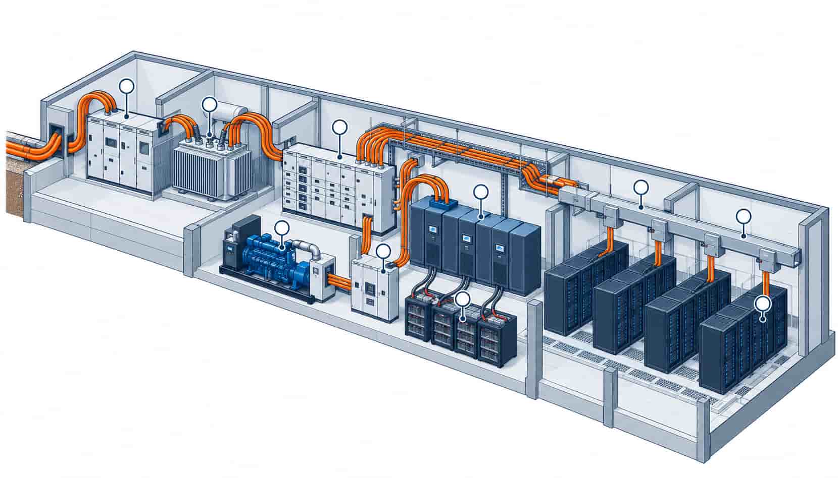
Follow one megawatt from the grid to a server and it passes through a surprisingly short, fixed sequence: utility intake, MV switchgear, transformer, LV switchboard, transfer node, UPS, row distribution, rack PDU, server. Each hop has its own cable family, its own governing standard, and its own failure personality. Facilities that document the chain this way commission faster, audit cleaner and expand without surprises, because every question — what cable, what standard, what route, who owns it — has a written answer before the drums arrive.
This article walks the chain in order and maps the cable at each hop, organizing the products by position in the power system rather than by family. It draws on the equipment-side context in our data center power collection, and the standards referenced at each hop are mapped across rulebooks in our IEC, GB and BS cable standards overview.
Hop 1: Utility Intake to MV Switchgear
The chain begins at the point of supply, where medium voltage arrives on the campus — typically 11 kV, 20 kV or 33 kV. The cable here is single-core or three-core XLPE at 8.7/15 kV to 26/35 kV, screened construction with a designed screen earthing scheme, routed from the intake room or substation to the MV switchboard. Specification attention concentrates on three points: the screen bonding scheme sized against circulating currents, non-magnetic containment on single-core AC runs, and sheath performance for the sections that pass through ducts or trenches. This is also where the utility’s own requirements attach — their approval often governs cable type, terminations and testing regardless of what the project standard says.
Documentation discipline starts here too: the intake route is the one part of the chain the operator did not build, so the as-built record — lengths, drums, test results, screen earth values — must be created at handover, because it will never be as easy to reconstruct later.
| Chain Hop | Cable Family | Governing Standard | Watch Point |
|---|---|---|---|
| Utility intake to MV switchboard | 8.7/15 to 26/35 kV screened XLPE | IEC 60502-2 | Screen bonding; non-magnetic containment |
| MV switchboard to transformer | MV XLPE, short runs | IEC 60502-2 | Termination kits matched to transformer bushings |
| Transformer to LV switchboard | 0.6/1 kV heavy feeders or busduct | IEC 60502-1 / IEC 61439 | Short, heavy, well-supported runs |
| Generator to ATS tie-in | 0.6/1 kV flexible parallel sets or MV feeders | IEC 60228 Class 5 / IEC 60502-2 | Vibration flex loop; drop at block pickup |
| UPS input and battery | Fine-stranded flexible 0.6/1 kV | IEC 60228 Class 5 | Grouping derating in UPS rooms |
| LV board to row distribution | LSZH feeders (WDZ-YJY class) | IEC 60332-3; IEC 60754; IEC 61034 | Tray fill and corrected ampacity |
| Row distribution to rack PDU | Busway tap-offs or branch circuits | IEC 61439 / project spec | Class 5 flexible at every termination |
Hop 2: Through the Transformer to the LV Board
The transformer is the chain’s voltage boundary and the cable’s quantity boundary: above it, few metres at high voltage; below it, most of the installation’s copper. The MV side is short — termination quality dominates. The LV side runs heavy 0.6/1 kV feeders or busduct from the transformer to the main switchboard, and despite the short length these runs deserve respect: they carry the full load of everything downstream, they run warm, and their support and expansion provisions are what keep a hot, heavy feeder from becoming a maintenance item. The sizing logic upstream of this hop — matching transformer capacity to the load study — is developed in our transformer capacity sizing guide.
From the LV board downward, the chain splits by function: critical paths through UPS plant, essential paths to mechanical plant, life-safety paths on fire-rated circuits. Mapping means giving each branch its own identity in the schedule — source board, path designation, route ID — from the very first feeder, because retrofitting path labels into a built distribution is a documentation project nobody wants.
Hop 3: The Backup Node — Generator and UPS
Two plant families insert themselves between the LV board and the row, and each reshapes the cable map around it. The generator plant ties in through the transfer node: flexible parallel sets sized for sustained duty and block-load pickup, with voltage drop and vibration considerations that make generator feeders their own specification exercise — sustained ampacity in a hot plant room at one end, clean transfer at the other. The switching logic at that node, ATS versus STS, is compared in our transfer technology analysis.
The UPS plant adds its own hops: input feeders from the board, battery connections in fine-stranded flexible copper sized as much for heat and termination as for ampacity, and output feeders whose grouping derating in a warm UPS room surprises every first-time specifier. The load side of the UPS hop is covered in our UPS sizing guide; the cable side follows the corrected-ampacity method in our cable size selection guide.
Hop 4: Row Distribution and the Last Metres
Below the UPS, the chain enters the hall and becomes a distribution problem: LSZH feeders from the board to row busways or PDU panel boards, tray routing through hot aisles, and the hand-off to rack PDUs through busway tap-offs or branch circuits. The last metres are where density decides topology — busway spine above roughly 20 kW per rack, parallel feeders below — and where Class 5 flexible stranding earns its place at every termination that sees vibration or rework. The equipment choice at that final hand-off, floor versus rack PDU, is compared in our PDU selection guide.
What makes the last metres tractable is the same thing that makes the whole chain tractable: a schedule where every cable carries its hop, its path and its route, and every drum label matches. The chain from intake to rack is only long on paper; on site it is a sequence of short, well-documented hops — or it isn’t, and commissioning finds out which.
| Document | What It Must Show | Why It Matters |
|---|---|---|
| Single-line diagram | Every hop, source, and redundancy path | The chain's electrical truth |
| Cable schedule | Hop ID, cable family, standard, route ID per line | Links drawings to drums |
| Routing plan | Tray routes, crossings, separations per hop | Makes the physical layout auditable |
| Drum labeling | Route ID and hop on every drum and both ends | Site verification without guesswork |
| Test records | Batch and commissioning tests filed per route | Baseline for the lifecycle file |
When a Chain Map Is Not the Answer
A document is not a design. The chain map records decisions; it does not make them, and copying a chain from a previous project transfers its assumptions — load density, redundancy mode, market standards — along with its structure. Each hop deserves its own calculation, and the map earns its value only when the numbers behind it are the project’s own.
There is also a limit to hop-level thinking: the chain interacts. Generator feeder length affects voltage drop at transfer; UPS room grouping affects battery cable sizing; tray congestion at the hall affects everything downstream of it. The map’s highest use is not as a checklist but as a coordination surface — the one drawing where every discipline can see what its decisions do to the neighbors.
RFQ Checklist: Buying the Chain as One Scope
Whether the chain is quoted hop by hop or as one package, the RFQ should carry:
- Single-line diagram with every hop and redundancy path marked
- Cable schedule by hop: family, standard, routed length, correction factors
- Voltage classes at each level, stated explicitly
- Fire performance per route class: LSZH distribution, fire-rated life safety
- Flexible stranding and termination requirements per hop
- Drum lengths matched to routing, labeled by route ID
- Batch test reports and type test documentation per family
- Delivery phasing aligned to the construction sequence of the chain
- Single supplier or split-supplier decision, stated with rationale
- Copper price linkage covering the full delivery window
One supplier across the chain has a real advantage here: one quality system, one documentation format, one copper basis — and one throat to choke when two hops disagree. Kexingyu Cable Group (KXYE) produces every family in this map, from 26/35 kV screened XLPE to fine-stranded UPS connections and fire-rated circuits, under one roof with copper price linkage across the order.
Conclusion
The power chain is short on hops and long on consequences. Map every hop with its cable, standard and route; give each branch its identity from the first feeder; and buy the scope with the documentation discipline that makes every drum traceable to the drawing. Facilities that do this commission the way the drawings promised.
Bring us the single-line and the load schedule, and Kexingyu Cable Group (KXYE) will quote the chain hop by hop — one factory group, one quality system, one metal basis, from the intake to the last metre behind the rack.
Recent Posts
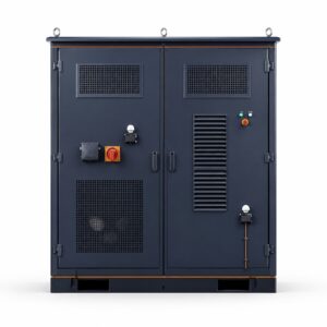
Thermal Runaway in Lithium Batteries: What BESS Buyers Should Understand
Thermal Runaway in Lithium Batteries: What BESS Buyers Should Understand How thermal runaway starts, how it propagates, and which evidence buyers should require before approving
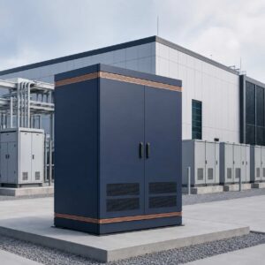
Energy Storage for Data Centers: A Growing Backup Power Option
Energy Storage for Data Centers: A Growing Backup Power Option Batteries have always backed up data centers in the form of UPS strings. Grid-scale BESS
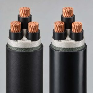
YJV vs YJY: Reading Chinese Cable Designations Like a Local
YJV vs YJY: Reading Chinese Cable Designations Like a Local YJV vs YJY: Reading Chinese Cable Designations Like a Local Quick Answer: YJV and YJY