
Procuring 110kV and 33kV Incoming Supplies for Hyperscale Data Centers: Voltage Choice, Equipment and Lead Times
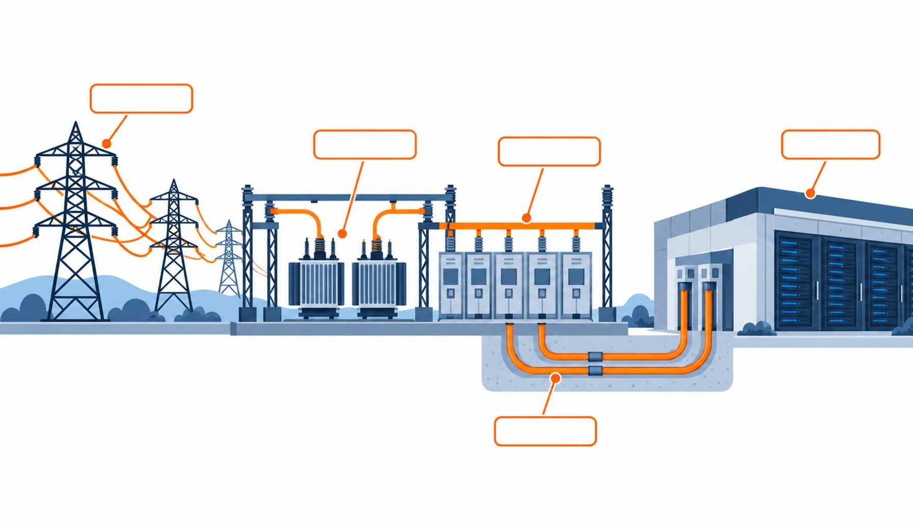
Quick Answer: The incoming voltage is settled long before detailed design, and it decides how many transformers and switchgear bays you buy, how much land the substation takes and how long the connection takes to energise. A 110kV supply suits a campus that can fill a large load block in one go. A 33kV supply suits a campus built in phases or one where the utility will not release 110kV capacity. The technical data that matters most to a supplier is the fault level, the earthing arrangement and the transformer impedance range, and all three should be in the enquiry rather than in a later revision.
Introduction
A hyperscale campus begins with a number that is not equipment: the load it intends to draw at full build. That number, divided by the capacity a single circuit can carry, produces the incoming voltage. Everything else in the power chain follows from it, including the number of transformers, the size of the switchyard and the duration of the utility approval.
Buyers usually meet this decision late and treat it as an engineering outcome. It is better treated as a procurement input. Our note on data center power demand growth sets out how quickly the underlying load has moved, and our note on the switchgear and transformer shortage covers why the equipment behind this choice now arrives on a clock measured in years.
What the Voltage Choice Actually Changes in the Purchase
The voltage is not a label on a drawing. It changes the bill of materials in five places.
Transformer count and rating. A 110kV supply can land 60 MVA or more on one unit, so a large block of load is served by two or three transformers. A 33kV supply moves roughly 20 to 40 MVA per circuit, so the same load is served by more units, more protection and more cable.
Switchgear bays and their fault rating. Fault level at 110kV is usually higher than at 33kV, so the switchgear is a different class of equipment with a different test certificate and a different lead time. The bay count also changes, because the number of incomers, bus sections and outgoing feeders all scale with the number of transformers.
Land, buildings and clearances. A 110kV installation needs a switchyard or a gas insulated building, a larger separation to occupied areas and a compliant access route. That is civil cost and permitting time, both of which are easier to fund at masterplan stage than to retrofit.
Losses and cable quantities. Higher voltage means lower current for the same power, so the incoming cables are smaller and fewer. That is a real saving on a campus where the substation is far from the halls, and it partly offsets the cost of the higher-rated equipment.
The Decision Table: Incoming Supply Options Compared
The four options below cover most hyperscale enquiries. The table sets out what each one commits the buyer to.
| Option | What You Are Buying | What to Specify | Evidence You Should Receive | Lead Time Shape and Risk |
|---|---|---|---|---|
| Dual 33kV incomers | Two 33kV circuits, a bus section, two or three transformers at 20 to 40 MVA, and the protection to run them in parallel | Fault level in kA, earthing method, transformer impedance and tap range, protection scheme and interlocking | Type test certificates to IEC 62271, transformer routine tests to IEC 60076, protection setting schedule | Shorter switchgear lead time than 110kV; more bays, more cable, more terminations to install and witness |
| Single 110kV incomer | One 110kV circuit, a gas insulated or air insulated installation, and two large transformers in the 60 to 100 MVA class | Fault level, transformer impedance and cooling class, noise limits, clearance and access arrangement | Switchgear type tests, transformer routine and impulse test reports, full scheme drawings before manufacture | Long equipment lead time; capacity is committed before the campus can fill it, so the load programme has to be credible |
| Dual 110kV incomers | Two independent 110kV circuits with bus coupler, four or more transformers, and full protection duplication | Independence of the two circuits, transfer scheme, synchronising arrangement, and the N-1 case in writing | Utility independence confirmation, protection coordination study, staged energisation plan | Highest cost and longest approval; the design case has to be defended, not assumed |
| Utility substation with 33kV handover | A 110kV substation built and owned by the utility, with the campus buying 33kV feeders from it | The interface point, the protection boundary, the metering arrangement and the capacity reservation terms | A connection agreement with a capacity figure, an interface schedule and a metering diagram | Lowest capital cost to the campus and the least control over schedule; capacity upgrades depend on other users |
Specifying the Incoming Supply Package
Enquiries for high voltage equipment are lost on missing data rather than on price. Six items decide whether a bidder can quote accurately.
Fault level and its basis. The prospective short circuit current at the point of connection, stated in kA for one and three seconds, with the source study it came from. Where the figure is provisional, say so, because cable and switchgear ratings are selected against it.
Earthing arrangement. Solid, resistance or impedance earthed, and whether the neutral is distributed. This decides the transformer winding configuration, the protection settings and the cable screen design. Our note on the IEC 60076 transformer standard covers the test evidence that should come back with it.
Transformer impedance, tapping and cooling. Impedance percentage and tolerance, the on load tap changer range, and whether cooling is ONAN, ONAF or forced. Impedance sets the downstream fault level, so it is a protection input as much as a purchasing line item.
Instrument transformers. Ratio, burden, class and short time rating for the current transformers, and the accuracy class of the voltage transformers used for metering. Where the utility meters on your side of the boundary, its requirements decide these, not yours.
Protection and control. Whether the protection scheme is duplicated, whether the interlocking is hardwired or software based, and what interfaces to the site supervisory system are expected. These determine the amount of site wiring, which is where the installation cost surprises are.
Environmental and site data. Ambient temperature range, altitude, pollution level and seismic zone. The pollution level in particular changes creepage distances and therefore the equipment class, and it is cheap to declare and expensive to discover.
Where the Lead Time Actually Sits
The programme for a grid connection is usually drawn as one line. In practice it is three clocks running at different speeds.
Transformer. This is the long one. Lead times for large power transformers have been reported by analysts such as Wood Mackenzie at 80 weeks and beyond, with some project specific units quoted well past that. Size, cooling class and tap changer specification all push the order later, so the transformer enquiry belongs at masterplan stage rather than at detailed design.
Switchgear. High voltage switchgear is also constrained, and the constraint differs by type. Gas insulated equipment sits on a different line from air insulated, and the bay count you need is fixed by the voltage decision above. Our note on switchgear lead times sets out what can be pulled forward and what cannot.
Approvals. The grid connection and the utility interface usually take longer than both of the equipment clocks, and they cannot be shortened by paying more. Where a campus has a fixed energisation date, the approval path is the critical path, and equipment orders placed before approval are bought on a promise.
What to Freeze Before the Order
| Item | What to State | Evidence to Attach | Cost of Leaving It Open |
|---|---|---|---|
| Voltage and capacity | The selected voltage, the firm capacity in MVA and the load block it is intended to serve | A load schedule with a growth step, signed by the load owner | A connection sized for a load that never materialises, or an upgrade application made twice |
| Fault level and basis | Prospective short circuit current in kA with duration, and the source of the figure | The utility study or a recognised calculation, labelled provisional if it is | Equipment ordered with the wrong rating, discovered at protection coordination |
| Earthing and neutral | The earthing method and whether the neutral is distributed to the campus | A single line diagram with the earthing shown at each level | Transformer and cable changes after manufacture, or a protection scheme that cannot be set |
| Transformer specification | Rating, impedance and tolerance, tap range, cooling class, noise limit | A technical schedule with the values that will be tested | Parallel operation problems, or noise limits missed at commissioning |
| Protection and interface | Whether protection is duplicated, and what the utility requires at the boundary | A protection philosophy note and an interface schedule agreed with the utility | Site wiring added late, or a boundary that fails its first approval test |
| Metering and boundary | Where ownership changes, and who meters at that point | A metering diagram with class and ratio of each instrument transformer | Repeated disputes over energy and availability figures, and metering replaced later |
| Site conditions | Ambient range, altitude, pollution level and seismic zone | A site condition statement referenced in the specification | Equipment derated or rebuilt after delivery, and a warranty argument about the cause |
| Delivery, storage and tests | Delivery split, storage requirements, and the tests to be witnessed at the factory | A programme showing delivery windows and a witness point schedule | Equipment arriving before its building, storage damage, and tests repeated on site |
When 110kV Is Not the Answer
Where the load build is genuinely phased. A campus that will fill one hall in the first two years and the rest over five should not commit to a capacity block it cannot use. The utilities charge for reserved capacity and the equipment ages in storage.
Where the utility owns and builds the substation. Handing the 110kV installation to the utility removes capital cost and schedule control. That trade is right for some developers and wrong for others, but it should be a decision rather than a default.
Where the site has no realistic route for a high voltage line. A 110kV connection needs an overhead or underground route, and the route is often the hardest approval of the project. Where the route is uncertain, a 33kV supply with a staged upgrade is a safer purchase.
Where the design has not considered two levels. Some campuses are best served by 110kV on site with a 33kV or 11kV distribution layer, rather than 110kV straight to the load. That arrangement costs an extra transformer stage and saves a great deal of low voltage cable. Our note on compact substations for data centers covers where that layer pays for itself.
RFQ Checklist
- Selected voltage and firm capacity stated, with the load schedule that justifies them
- Fault level in kA at the point of connection, with its source and status
- Earthing arrangement and neutral policy stated at every voltage level
- Transformer rating, impedance, tap range, cooling class and noise limit scheduled as tested values
- Instrument transformer ratios, burdens and classes shown separately for protection and metering
- Protection duplication and utility boundary requirements agreed in writing
- Pollution level, altitude, ambient range and seismic zone declared
- Delivery split, factory witness points and storage requirements in the purchase order
- Confirmation of who owns and maintains each item either side of the interface
- Approval programme attached, showing what the order depends on
- Spare parts list agreed at order, not at handover
- Site acceptance tests defined before delivery, with the records that close them
Conclusion
The incoming supply is the most consequential purchase on a campus and the one made with the least information, usually on a provisional fault level and an assumed load. The remedy is not more analysis. It is to declare what is known, label what is not, and place the transformer enquiry against the earliest credible load figure, because that is the clock that cannot be recovered once it is lost.
Kexingyu Cable Group (KXYE) supplies the equipment that sits on both sides of this interface, including the KYN28 medium voltage switchgear used on the distribution level, the transformers and substation range together with medium voltage cable for the feeder routes, and the low voltage distribution that takes the supply into the halls, from one factory group with copper price linkage on project-scale orders. Send the load block you intend to serve and the fault level you have been given, and we will return the ratings, the test records and the lead times that fit; the fastest route is a request for quotation.


