
Procuring Dual-Source Incoming Supplies for Data Centers: Independence, Transfer and What to Verify
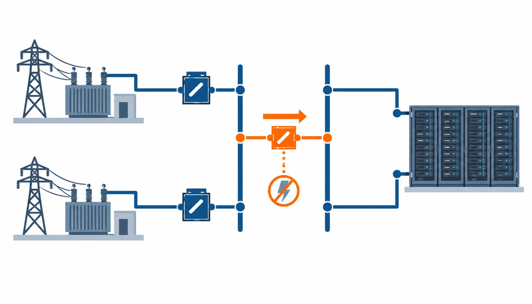
Quick Answer: Two supplies are only two sources if they are independent, and independence is a property of the network rather than of your switchgear. Buy the second source by proving where it comes from, then specify the switchgear that transfers between them: the bus arrangement, the transfer logic, the interlocking and the load step the scheme can actually carry. The most expensive mistake in dual-source procurement is a second feeder that shares a transformer, a corridor or a substation with the first.
Introduction
A dual-source supply is usually specified as a line on a schematic, with two arrows entering a switchboard. Whether it deserves the redundancy credit it is given depends on information the buyer rarely asks for: where each circuit comes from, how far apart the two paths stay and what the utility does at that substation during maintenance.
The equipment side of the purchase is well understood. The network side is not, and it is where the value sits. Our note on redundant power feeds and cable covers the downstream half of the same question, and our note on utility grid expansion explains why a second circuit is now an application rather than a purchase.
What Independence Actually Means
Utilities describe a supply as independent when a single fault, or a single planned outage, cannot remove both circuits. That definition is stricter than it looks, and it has four consequences for procurement.
Different source substations. Two circuits from the same substation share its busbars, transformers and protection, so a fault on the busbar removes both. This is the most common way a dual supply turns out to be a single supply with two names.
Separated routes. Two circuits that share a cable trench, an overhead corridor or a tower for part of their run have a common exposure. The separation distance matters, and it should be stated in metres rather than described as separate routes.
Independent switching and protection. If both circuits are protected by the same relay scheme or switched by the same operator action, a mistake can take out both. Independence includes the control arrangements.
Maintenance compatibility. A utility may take one source out for planned work at the same time as it takes the other out for unrelated work. The connection agreement should state the notification and the constraint, otherwise the redundancy is theoretical during the very periods when it is needed.
The deliverable to ask for is a written independence statement, with the source substations, the route separation and any shared assets named. Where a utility will not provide one, the design assumption should be that the supplies are not independent, and the standby generation becomes the real second source.
The Decision Table: Dual Supply Architectures Compared
The four arrangements below are the common ways of turning two incoming circuits into a usable supply.
| Arrangement | What You Are Buying | What to Specify | Evidence You Should Receive | Cost and Failure Mode |
|---|---|---|---|---|
| Single busbar with coupler | Two incomers, one bus section and an automatic transfer scheme that closes the coupler when a source is lost | Coupler rating, transfer logic, transfer time, load step limits, interlocking and protection blocking | Utility independence statement, protection coordination study, timed transfer test records on load | Lowest cost and the most common choice; a failed transfer closes a coupler onto a fault unless blocking is proven |
| Duplicate busbars | Two busbars each fed from its own incomer, with each load connected to both through changeover devices | Which loads are duplicated, changeover device type, busbar rating, and the maintenance state of one busbar | Duplication schedule, changeover test records, drawings showing every load on both busbars | Higher cost and more space; the failure mode is a load that was assumed duplicated but is fed from one busbar only |
| Ring main arrangement | Incoming circuits connected in a ring, with each substation or switchboard fed from two directions | Ring configuration, protection scheme for ring operation, and the isolation method for a faulted section | Protection study for open and closed ring operation, isolation and restoration procedure | Good cost per point of redundancy; faults require a switching sequence and the procedure is part of the purchase |
| Mechanical transfer switch | A discrete changeover device that physically moves the load between two sources | Rating, number of poles, switching time, service and withstand rating, control and manual override | Type test certificates, switching time records, a live transfer test with the expected load connected | Simple and easy to witness; a transfer time that the IT load can tolerate has to be confirmed, not assumed |
Buying the Transfer Scheme
The transfer scheme is where dual supplies succeed or fail, and it is specified in five parts.
The transfer logic and its timings. Whether the scheme transfers automatically, the detection time, the dead time and the total restoration time. These should be stated in seconds and tested against the load’s ride through capability rather than against a general service level.
The load step. The amount of load the scheme can transfer in one operation, and whether it is transferred by closing the coupler or by breaking before making. Where the transfer is break before make, the IT load sees a supply interruption, and that is a specification decision with a cost attached.
Blocking and interlocking. The conditions under which the transfer must not operate, and the mechanical and electrical interlocks that enforce it. A transfer that operates onto a healthy busbar feeding a fault is worse than no transfer at all.
The protection interface. How the two incoming protections coordinate so that a fault on one source does not trip both, and what settings are exchanged with the utility. Our note on automatic and static transfer sets out where a static device belongs instead of a mechanical one.
The operating interface. What the operations team sees and can control, including the ability to block the scheme during work and a clear indication of which is the healthy source. This is what prevents an operator from defeating the redundancy without knowing.
What to Verify Before Handover
Dual supply schemes are commissioned by testing, and the tests are the only evidence that the purchase works.
Timed transfer on load. The scheme is operated with the expected load connected, with the transfer time measured at the load, not at the relay. A transfer that completes in 200 milliseconds at the switchboard may take longer at the load once contactor drops and power supply hold up times are included.
Transfer in the wrong direction. The scheme is proven to work from either source to the other, not only in the direction the designer had in mind. Asymmetric schemes are common and only show up during a real outage.
Blocking function test. The conditions that should prevent transfer are injected, and the scheme is confirmed not to operate. This is the test most often skipped and the one that matters most. Our note on N+1 and 2N redundancy describes how the resulting configuration should be documented.
Phase and rotation check. Both sources are confirmed to be in the same phase rotation and the same phase relationship before any parallel or momentary parallel operation is permitted. Where the two sources are not in phase, transfer has to be break before make, and that constraint belongs on the drawing.
What to Freeze Before the Order
| Item | What to State | Evidence to Attach | Cost of Leaving It Open |
|---|---|---|---|
| Independence evidence | Source substations, route separation in metres, and shared assets if any | A written independence statement, or an acknowledgement that it is not independent | A redundancy claim used in the design case that the network does not support |
| Transfer scheme type | Automatic or manual, and whether it is break before make or momentary parallel | A transfer scheme description with the logic and the timings | Switchgear built for one scheme and commissioned against another |
| Timing and load step | Detection, dead and restoration times, and the maximum load transferred in one operation | A time and load schedule compared with the load ride through capability | A transfer that is fast enough on paper and slow enough in practice to drop the load |
| Blocking and interlocking | The conditions that must prevent transfer, and how they are enforced | A blocking matrix, plus the interlock schedule to be tested | Transfer onto a faulted busbar, converting one source fault into a total outage |
| Protection coordination | Settings, grading margins, and what is exchanged with the utility | A coordination study covering both sources and the coupler | One fault tripping both incomers, with the scheme unable to recover |
| Coupler and device ratings | Short time withstand rating of every device that carries load after transfer | The rated values compared against the fault level at the busbar | Devices that cannot close onto the available fault current safely |
| Phase and rotation | The relationship between the two sources and the permitted operating modes | A phase rotation record for both sources, taken on site | A parallel operation that is not possible, discovered at commissioning |
| Testing and records | The witness points, the load at which transfer is tested, and the records to be issued | A test schedule with measured values and pass criteria | A scheme accepted on relay indications rather than on measured transfer performance |
When Dual Supply Is Not the Answer
Where the second circuit is not genuinely independent. A second feeder from the same substation adds cost and adds a switching risk without adding redundancy. Money spent making the first supply robust, or on generation, may be better placed.
Where the transfer time cannot meet the load. A break before make transfer with a dead time measured in seconds is not a solution for a load that cannot tolerate it. Where the load cannot ride through, the answer is the UPS rather than the switchgear.
Where the coupler is bought without the blocking logic. The switchgear is the smaller part of the purchase. A dual supply scheme bought without the protection study, the blocking matrix and the transfer tests is a scheme that has not been bought at all.
Where the operations team will run it as a single supply. Redundancy that is routinely defeated by operating practice is a cost without a benefit. Where the site expects to run both incomers closed and to take supplies out without a procedure, the design should be simplified to match. The distribution arrangements downstream are described in our note on data center distribution.
RFQ Checklist
- Written independence statement from the utility, or an explicit statement that it is unavailable
- Route separation stated in metres, with shared corridors identified
- Transfer scheme type and mode stated, with detection, dead and restoration times
- Maximum load step per transfer stated and compared with load ride through capability
- Blocking matrix supplied, listing every condition that must prevent transfer
- Protection coordination study covering both sources and the coupler
- Short time withstand rating of the coupler and every device carrying load after transfer
- Phase rotation and phase relationship recorded for both sources
- Interlocking schedule issued for testing, covering mechanical and electrical interlocks
- Live transfer test specified at the expected load, with the measurement point named
- Operator interface requirements listed, including manual block and source indication
- Records required at handover, including measured transfer times and test pass criteria
Conclusion
A dual supply is bought twice: once as a cable and switchgear package, and once as a network arrangement that may or may not exist. The first is a normal procurement exercise. The second requires asking the utility a question it does not volunteer to answer, and accepting the answer even when it is inconvenient. Where the answer is that the supplies are not independent, the honest design puts the redundancy somewhere it can be proven.
Kexingyu Cable Group (KXYE) supplies the equipment that implements the transfer decision, including the dual power ATS cabinet used where a discrete changeover is preferred, the medium voltage switchgear and busbar connections for the incoming lineups, and the cable and terminations for the two feeder routes, from one factory group with copper price linkage on project-scale orders. Send the two source arrangements and the load you need to transfer, and we will return the ratings, the interlocking schedule and the test records that demonstrate the scheme works in both directions; the fastest route is a request for quotation.


