
Strain Relief at the Connector Interface: What to Specify Before the Order
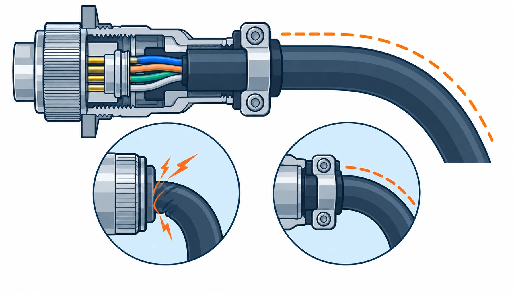
Quick Answer: Strain relief is the mechanical half of a connector interface, and it is almost never written down. Its job is to take tension, torsion and side load out of the cable before those loads reach the contact terminations, and the way you specify it decides where the cable is allowed to bend. Get it right and the harness fails nowhere; leave it to the assembly bench and the cable will break a few millimetres behind the shell, which is the hardest place in the whole system to find and the easiest to avoid at order time.
Introduction
Buyers spend their specification effort on the connector: family, pin count, current rating, IP class. The transition from that connector to the cable gets a line on the drawing at most, usually “cable entry per supplier standard”. That gap is where the money goes later. A harness does not usually fail at the contact or in the middle of the run; it fails at the point where the cable leaves a rigid shell and has to become flexible again, and that point is set entirely by the strain relief you did or did not specify.
The harness overview in our note on robot harnesses and connectors treats the assembly element by element. This guide stays on one element: the cable entry, the load path it creates and the evidence that proves it was designed rather than improvised.
What Strain Relief Actually Does
Three loads arrive at a connector entry from a moving machine. Tension pulls the cable out of the shell. Torsion twists it as the axis rotates. Bending and side load push it against the edge of the shell every cycle. All three are normal in service; none of them should reach the crimp. Strain relief is the component that intercepts them, and its only real design decision is where it lets the cable start to move.
A well-designed entry holds the cable rigidly for a short distance behind the termination, then releases it gradually over a controlled length, so the flex point lands in a region of the cable that was built to flex. A badly designed entry does the opposite: it holds nothing, so the cable moves right at the contact, or it holds too hard and too sharp, so the cable fatigues against a hard edge. Both versions pass a bench continuity test, which is why the fault surfaces in the field.
The Five Ways to Relieve Strain
Relief hardware falls into five families, and they are not interchangeable. A backshell clamp compresses the jacket under a metal body and is the default on circular connectors. A cable gland seals and grips a jacketed cable at an enclosure wall. A molded boot is overmoulded onto the cable and shell together, so it becomes part of the assembly and cannot be loosened or removed. A strain relief spring spirals along the cable and spreads bending over its length. A bundled or clamped entry gathers several cables and grips them as a group where individual glands would not fit. The choice follows the environment and the load, not the connector datasheet alone.
The Decision Table: Relief Designs and Where Each Belongs
| Design | Where It Belongs | What to Specify | Evidence to Demand | Where It Fails in Service |
|---|---|---|---|---|
| Backshell clamp | Circular connectors on robot axes and cabinets; the default metal entry | Clamp range matched to jacket diameter, contact area, screen bond where shielded, torque value | Clamp range on the drawing and a first-article fit on the actual cable | Clamped at the wrong diameter, so the jacket slips or is crushed and the screen bond opens |
| Cable gland | Enclosure walls and junction boxes where the entry must also seal | Thread and IP class, sealing insert sized to the jacket, grip force, strain relief rating | IP test evidence and a gland sized to the measured jacket, not the nominal one | Gland sized to nominal jacket, leaving the seal loose on a cable at the low end of tolerance |
| Molded boot | Mobile and washdown machines where the entry must be tamper-proof and sealed | Moulding material and hardness, bond to jacket and shell, tooling ownership, first-article | Pull test on the finished moulding and sectioned first-article samples | Voids or poor adhesion at the shell, letting water track in along the interface |
| Strain relief spring | Hand-held tools and light robots where bending must be spread over a length | Spring length, diameter and end fixing so it does not slide along the cable | Bend cycle test with the spring fitted, showing movement away from the entry | Spring slides along the cable, concentrating rather than spreading the bend |
| Bundled entry | Dress packs and multi-cable entries where individual glands will not fit | Group clamping force, separation between cables, a service loop length per cable | Dressing drawing with clamp positions and a fitted sample | Cables clamped as a flat bundle, so inner cables chafe against their neighbours |
Bend Radius at the Entry: The Number to Write Down
The entry sets a minimum bend radius, and that radius is a property of the cable, not the connector. Write the number on the drawing as a distance measured from the face of the shell, because “keep the bend radius” means nothing to an assembler without a datum. For a flex-rated robot cable the dynamic minimum is the figure that applies, and it is often several times larger than the static one. Our note on cable minimum bend radius explains how the two are derived from the construction.
Two practical points follow. First, the relief must be long enough that the cable reaches its minimum radius after it has left the rigid zone, not inside it. Second, the routing between the entry and the first moving point needs enough slack to form that radius without pulling, which is why a service loop belongs in the drawing and not in the assembler’s judgement. Where the axis rotates as well as bends, the entry also has to cope with torsion, and the cable construction itself has to be torsion-rated for that duty.
What to Freeze Before the Order
| Item | What to State | Evidence to Attach | Cost of Leaving It Open |
|---|---|---|---|
| Relief family per entry | Backshell, gland, molded boot, spring or bundled entry named for each interface | An entry schedule mapped to the harness drawing | The bench picks whatever is in the bin, and the flex point lands at the contact |
| Entry bend radius | Dynamic minimum radius stated as a distance from the shell face | A routing drawing with the radius dimensioned | Cables bent tighter than their rating, fatiguing inside months |
| Grip diameter window | Clamp or gland range matched to the measured jacket, with tolerance | First-article fit on production cable, not a nominal sample | Loose grips that let the cable slip, or crushed jackets that damage the screen |
| Pull-out force | Minimum force the entry must hold before the cable moves, by cable size | Batch pull-out records traceable to shipped serial numbers | No proof of grip quality after a field fault pulls a cable out of a shell |
| Screen bond at the entry | How the screen is terminated at the shell and whether the entry carries it | 360-degree bond drawing, with transfer impedance evidence on request | EMC lost at the one point the shield cannot compensate for |
| Sealing at the entry | IP class required at the cable entry, stated separately from the mated pair | Seal test evidence on the assembly with the cable fitted | A sealed connector pair that still leaks through the cable entry |
| Service loop | Length and position of the loop between the entry and the first moving point | Dressing drawing with clamp positions | Assemblers pulling the loop tight, removing the slack the bend needs |
| Re-termination policy | Whether an entry may be re-clamped in the field, and with what tooling | A written procedure naming the tooling and torque | Field rework that undoes the very grip the specification paid for |
When a Strain Relief Specification Is Not the Answer
Where the termination itself is the weak point. If a cable breaks just behind the shell with no mechanical damage to the entry, the fault may be in how the contact was terminated, not in how the cable is held. Our note on terminating robot harnesses separates a joint failure from an entry failure, and the two are fixed in different places.
Where the entry is being asked to fix a routing problem. No strain relief compensates for a cable routed around a tight corner or run with no slack at all. If the machine geometry leaves no room for a correct radius, the answer is a longer cable, a different route or a torsion-rated construction, not a heavier clamp.
Where a molded boot is specified on a serviced joint. If the contact has to come apart in the field, moulding the entry shut makes every repair a cable replacement. On high-value harnesses that trade needs writing down: sealing and tamper resistance on one hand, serviceability on the other. Our note on overmolded harness assemblies sets out when moulding earns its tooling cost and when it does not.
Where the environment was judged only at the mated pair. A connector rated for washdown still fails if the cable entry lets water in behind the seal. The sealing conditions at the entry are judged on their own and are covered in our note on IP ratings for robot connectors.
Where the entry sits in a moving chain. Inside a drag chain the geometry does the work and the entry has a different job; the cable and the chain have to be considered together, as our note on drag chain cable explains, and a spring that works on a hand-held tool does nothing useful in a carrier.
RFQ Checklist
- Relief family named per entry: backshell, gland, molded boot, spring or bundled entry, with the interface it serves
- Entry bend radius stated as a distance from the shell face, using the dynamic minimum for flexed routes
- Clamp or gland range matched to the measured jacket diameter and its tolerance, not the nominal figure
- Minimum pull-out force per cable size, tested per batch with records traceable to shipped serial numbers
- Screen termination method at the entry specified where the cable is shielded, with a 360-degree bond drawing
- IP class stated separately for the cable entry, with seal test evidence on the assembly as fitted
- Service loop length and clamp positions shown on the dressing drawing
- Moulded entries to carry a first-article section sample and a pull test on the finished moulding
- Written policy on field re-clamping and re-termination, naming the tooling and torque values
- Sample qualification covering the finished entry on production cable, not only the connector datasheet
Conclusion
Strain relief is cheap to specify and expensive to skip, because it decides where the cable is allowed to bend. Name the relief family per entry, put a number on the entry bend radius, and ask for the grip and pull-out evidence that proves the entry was designed for the cable you are actually buying. None of that adds cost at order time; all of it moves failures away from the hardest place on the harness to repair.
Kexingyu Cable Group (KXYE) supplies the cable side of these interfaces: the continuous flex and torsion constructions whose jacket, stranding and screen geometry are built to be gripped at the entry and to flex where the relief releases them. Send us the routing, the connector schedule and the jacket measurements, and we will return constructions and sample lengths that fit; the fastest route is a request for quotation.


