
Robot Harnesses and Connectors: Specifying the Other Half of the Cable System
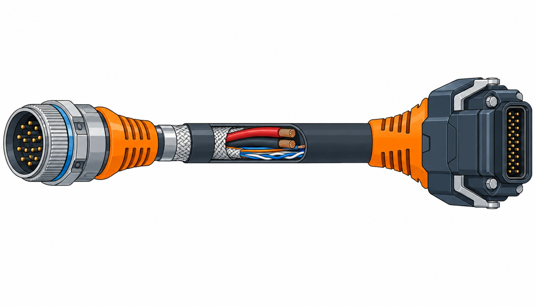
Quick Answer: A robot harness is two products sold as one: the cable, built to flex, and the connector system, built to make and hold contact under vibration. Most buyers specify the first in detail and buy the second as an afterthought, and that is backwards. In service, the connector interface, the terminations and the strain relief fail far more often than the conductor they are attached to. This guide sets out the harness element by element: what to specify, what evidence to demand, and the decisions to freeze before an order rather than after a line stop.
Introduction
Ask a robot integrator what they buy from a cable company and the answer is a part number for a continuous flex cable. Ask the same integrator where their field failures come from and the answer moves to the ends: connectors that back out, contacts that fret, glands that leak, overmolds that crack where the cable leaves the shell. The two halves are specified and sourced differently, ordered from different suppliers half the time, and joined by a termination process that belongs to neither of them.
That gap is worth closing at procurement level. Published market estimates put connector demand for automation and robotics at roughly twelve to thirteen billion US dollars in 2026, which tells you the connector half is an industry in its own right with its own standards and failure modes. A buyer who treats a harness as a cable with plugs on the ends will specify flex life and then discover that uptime was decided at the contact interface. Our special cable range page shows the cable families that carry the flex duty; this note deals with what sits at both ends of them.
What a Harness Actually Is
A robot harness is an assembly, and every element in it has its own specification and its own evidence:
The cable body. Power cores, signal pairs and data pairs, often with individual screens, laid up for the duty: torsion for the wrist, bend for the joints, continuous flex for the chain run. This is the part buyers specify best, and our notes on drag chain cable and on choosing between continuous flex and drag chain constructions cover the detail.
The connectors. Circular connectors in the M8, M12 and M23 families for sensors, feedback and servo power, and heavy-duty rectangular connectors for main feeds and cabinet interfaces. Each family has its own coding, contact size, current rating and sealing system, and once a platform standardises on a family it rarely changes.
The terminations. Crimps, solder joints and insulation displacement contacts that join conductor to contact. Termination quality is invisible after assembly and is the most process-dependent element in the harness.
The strain relief and overmold. The gland, boot or molded transition that takes the bending moment off the termination and carries it into the jacket. It sees every flex cycle the cable sees, and it is the most common crack site on a harness assembled well but transitioned badly.
Each element is bought, tested and failed differently, and a specification that names only the cable leaves the other three to whoever assembles the harness.
Why the Connector Half Decides Uptime
The arithmetic of robot duty is unkind to contact interfaces. A six-axis arm running a normal production cycle makes millions of small movements a year, and every one arrives at the connectors as micro-motion between contact and pin. Add drive vibration, temperature swings and washdown, and you have the environment connector engineers design against.
Field experience across automation fleets is consistent on this: intermittent faults cluster at connectors and terminations, not in the conductor bulk. A broken conductor is a clean failure that a continuity test finds. A fretted contact passes bench testing and fails on the third shift, which is the failure that costs a plant its output. The servo and feedback circuits are the most exposed, because they carry the encoder signals the drive needs to close the loop; our notes on servo cable construction and on encoder cable describe the cable side, and the same logic applies to the connectors those cables land on.
The procurement consequence is simple: the connector half deserves a specification with the same discipline as the cable half. The table below is what that looks like element by element.
The Decision Table: Harness Elements and What to Specify on Each
Read the last two columns if you are under time pressure: what drives cost and delivery for each element, and where each fails in service, which is where the money goes.
| Harness Element | What to Specify | Evidence to Demand | Cost and Lead-Time Driver | Where It Fails in Service |
|---|---|---|---|---|
| Power connectors (M23, heavy-duty rectangular) | Family and coding, contact size and current rating at the declared duty, voltage rating, mating cycles, locking mechanism | Rated current and voltage at the stated contact count, mating cycle figure, insertion and withdrawal force data | Inserts and housings are stock items; assembly and testing drive lead time | Contact fretting under vibration, locking tabs broken by rough mating |
| Signal and feedback connectors | Coding that matches the platform, contact plating, screening concept, pairs assigned to individual contacts | Screen termination method, attenuation data where the circuit is fast, plating specification | Coded variants multiply quickly; agree a platform list before ordering | Intermittent encoder faults from micro-motion and from screen pigtails |
| Data connectors (Ethernet, fieldbus) | Category or speed grade through the whole path, shielding class, IP rating of the mated pair | Channel test report to the declared category, sealing evidence for the mated condition | Certified data connectors carry a price step; one family across the platform recovers it | Contact contamination after washdown, category lost through one non-compliant element |
| Cable body | Flex duty as bend radius, torsion degrees per metre and cycles; oil, coolant and temperature exposure; core and screen construction | Flex test report at the stated radius and cycle count, screen coverage figure, material declarations | Continuous flex constructions cost more than catalogue flexible cable; custom lay-ups lengthen lead time | Jacket wear at clamp points, corkscrewing after torsion beyond rating |
| Terminations | Crimp rather than solder on moving axes, tooling and process standard named, pull-off force requirement per contact size | Crimp cross-section or pull-off force records from the harness batch | Qualified termination work is a service cost; changing supplier re-opens qualification | High-resistance joints that heat and drift, escapes that pass visual inspection |
| Strain relief and overmold | Gland or boot type, clamping diameter matched to the jacket, bend protection length, overmold material and adhesion | Bend cycle test at the transition, overmold pull-off force, temperature rating | Molding tools are amortised per variant; a custom overmold is a tooling order | Cracks at the jacket-to-overmold bond, cables levered against gland edges |
Specifying the Cable Half of the Assembly
The cable inside a harness carries a different duty from cable in a tray, and it is specified differently. Three numbers matter more than everything else on the datasheet.
Bend radius, stated at the worst point. A harness has its tightest radius where the cable enters the connector shell or the strain relief, not in the middle of the run. The datasheet figure applies there, not just to the cable body. If the gland design forces a tighter radius than the cable allows, the assembly fails at the transition. Say the radius, say where it applies, and require the test that proves it at that point.
Torsion, in degrees per metre. Wrist and arm harnesses twist as well as bend. A construction rated for bend flex will corkscrew under torsion duty it was never built for, and the failure shows up as core breakage some distance from the connector, which misleads the diagnosis toward the cable when the real fault is a duty mismatch. State degrees per metre and the direction of rotation.
Duty environment. Coolant mist, cutting oil, welding spatter and washdown chemicals each eliminate part of the jacket material range. On mobile platforms add UV and abrasion. List what the harness actually touches rather than hoping a general purpose PUR jacket covers it. Where the environment is a moving arm rather than a chain, the dress pack approach changes the harness shape entirely.
Termination and Workmanship
Termination is where a harness specification meets a manufacturing process, and the failure modes it produces are quiet ones. A cold crimp passes continuity at the bench, ships, and then develops a high-resistance joint under vibration. Nothing fails outright; the contact heats, the voltage drop drifts, and the machine reports faults nobody can reproduce on the bench.
The specification handles this with process requirements rather than inspection hopes. Name the termination method per conductor class: crimp for moving axes, where a solid joint concentrates bending stress at one point; solder acceptable only where the joint is static and strain-relieved. Name the standard the crimp process is controlled to and require pull-off force records from the actual harness batch, not from a qualification run a year ago. The failure these cheap clauses prevent is the most expensive kind of harness fault to chase, because it looks like a software problem for two weeks before anyone cuts the boot open.
Evidence and Acceptance Testing
A harness assembly can be verified before it ships, and the evidence set is not long. Ask for four things and tie them to the order.
Flex and torsion test reports run at the radius, torsion and cycle counts in your specification, not at the supplier’s house numbers.
Termination records from the batch: crimp height or pull-off force readings traceable to the serial numbers shipped. This evidence costs almost nothing when asked at order time and cannot be recreated afterwards.
Sealing evidence for the connector system in the mated condition, including the IP figure that applies once mated. An IP67 claim on an unmated connector is a marketing statement, not a duty rating.
Screen termination and data performance where the harness carries encoder or Ethernet circuits: the screening concept at the connector and a channel test where a category is claimed. Our note on robot cable sample testing sets out how to qualify a construction before volume, and robot cable certification covers the marks the destination market expects on the cable half.
What to Freeze Before the Order Goes Out
The harness decisions below are cheap at specification stage and expensive later. Freeze them in writing before the RFQ leaves.
| Item | What to State | Evidence to Attach | Cost of Leaving It Open |
|---|---|---|---|
| Connector families | Family and coding per circuit type, aligned with the platform standard | A connector schedule mapping circuits to families | Mixed families across a fleet and a doubled spare parts inventory |
| Current and voltage ratings | Rating per contact at the declared contact count and duty | Derating data at the stated contact count | Oversized, overpriced connectors, or contacts running hot at full load |
| Flex duty | Bend radius at the worst point, torsion degrees per metre, cycle target | Flex and torsion tests at those figures | A cable that met the datasheet and not the machine |
| Environmental exposure | Oil, coolant, washdown, temperature range, UV where outdoor | Material compatibility statements and jacket ratings | Jacket swaps after pilot failure, and a schedule slip to match |
| Termination method | Crimp on moving axes, process standard and tooling named | Batch pull-off force records | Intermittent joint faults that surface as software problems |
| Strain relief design | Gland type, clamping diameter, bend protection length | Bend cycle evidence at the transition | Harnesses that fail at the shell six months in, on a cable that tested fine |
| Screen termination | Screening concept per circuit, termination method at the connector | Screen coverage and termination detail drawings | Encoder noise faults fixed by adding ferrites instead of the joint |
| IP requirement | The figure required in the mated condition, per location | Sealing test evidence for the mated pair | Washdown zones serviced every quarter instead of every year |
| Qualification protocol | Sample tests before volume, acceptance criteria per test | A written qualification plan with pass thresholds | Volume shipments accepted on a sample nobody kept |
| Documentation set | Test reports, batch records and drawings delivered with each lot | A document schedule with owners and dates | Spare harnesses ordered years later without drawings to qualify them |
When a Harness Specification Is Not the Answer
Where the harness is blamed for a routing problem. Many harness failures trace back to how the harness was clamped, bent and dressed on the machine rather than to the part. If the prototype shows jacket wear at a clamp edge, the fix is a routing change or a dress pack, not a tougher cable; our note on dress pack cable walks through that distinction.
Where buying the connector separately is cheaper on paper and dearer in fact. Splitting the cable and connector halves across suppliers moves the interface risk to the buyer and voids the single point of accountability when a fault appears at the joint. Where practical, buy and qualify the assembly as one.
Where the platform is still moving. On a prototype humanoid or a first-generation mobile robot, connector families and routing will change. Investing in molded tooling before the design freezes is tooling spend that gets scrapped. Qualify the construction, keep the harness repairable, and leave the overmold for the frozen design. Our note on humanoid robot cable covers the prototype-to-production gap.
Where the spec was copied from another machine. A harness that works on a palletiser will not survive unchanged on a washdown food robot. Duty environment, IP requirement and termination method are machine-specific, and a copied spec imports the other machine’s assumptions silently.
Where price was the only question asked. The cost difference between a harness built to a real specification and one assembled from stock is modest against one line stop. It does not show in the quotation; it shows in the service data a year later.
RFQ Checklist
- Connector family and coding named per circuit type, aligned with the platform standard
- Current and voltage ratings declared at the stated contact count and duty
- Flex duty stated: bend radius at the worst point, torsion in degrees per metre, cycle target
- Environmental exposure listed: oil, coolant, washdown, temperature, UV where relevant
- Termination method per conductor class, with the process standard named
- Strain relief and overmold specified with bend protection length and jacket adhesion requirement
- Screen termination concept per signal and data circuit
- IP requirement stated for the mated condition, per machine location
- Flex, torsion and sealing test reports requested at the specified duty figures
- Batch termination records required with each shipment
- Sample qualification protocol agreed with pass criteria before volume release
- Documentation set scheduled: test reports, batch records, harness drawings
Conclusion
A robot harness earns its keep at the interfaces, and the interfaces are exactly the part of the assembly that a cable-first specification forgets. Name the connector families, express the flex duty where it is worst rather than where it is convenient, control the termination process, and demand evidence from the batch that ships. None of that adds much cost to the order, and all of it moves failures from the third shift back to the test bench.
Kexingyu Cable Group (KXYE) supplies the cable half of the assembly: continuous flex and torsion constructions for robot arms and drag chains, and the multi-element composite cable range that carries power, signal and data in one sheath. Send us the duty: radius, torsion, cycles, environment and the connector families you have standardised on, and we will return the constructions and test data that answer it. The fastest route is a request for quotation.


