
Buying Hybrid Connectors for Robots: Power, Signal and Pneumatics in One Interface
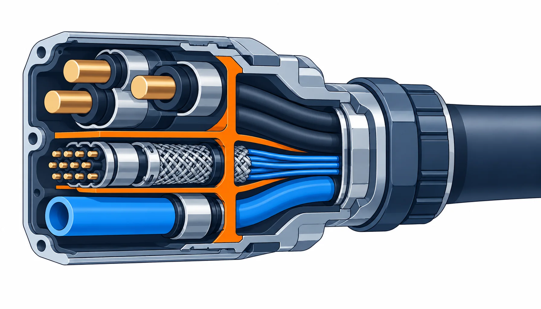
Quick Answer: A hybrid connector merges power, signal, data and sometimes pneumatics into one shell and one mating action. The gain is real: fewer cables in the dress pack, fewer mates at a changeover, and fewer places for a fault to hide. The price is equally real, because you have just put several risk domains, power, signal integrity, fluid sealing and EMC, into one part, and the specification has to keep them apart inside it. Buy hybrid when interfaces are the bottleneck and the volume justifies a custom insert, not to save a single cable.
Introduction
Every interface on a robot is a place where the machine can be assembled wrong and a place where a fault can start. A dress pack with six separate cables has six connectors, six entries, six seals and six chances to be mis-mated at the end of a long shift. A hybrid interface collapses that into one part, which is why it appears first on machines built in volume and on arms whose tooling is swapped often.
The harness overview in our note on robot harnesses and connectors treats the interface as one element among several. This guide stays on the hybrid interface itself: what goes inside it, what has to be kept apart, and what to write down before the insert is tooled.
Why Merge Interfaces at All
The case for hybrid is usually one of three. The first is changeover: a tool changer that has to separate power, signal and air in three actions costs cycle time every time it moves, and one mate removes two of those actions. The second is dress pack size and weight: on a moving axis, a lighter, tighter bundle flexes less and lasts longer, and a single hybrid cable is stiffer for its content than several round cables side by side only if the construction is done properly. The third is fault isolation: fewer interfaces means fewer places to look when an intermittent appears.
None of these is free. A hybrid insert is often a custom part with its own tooling, lead time and first-article approval, and its separation rules are stricter than those of any single-purpose connector. The buying decision is a volume decision: below a certain annual quantity the tooling and lead time outweigh the savings.
What Actually Goes Inside a Hybrid Interface
A hybrid shell contains zones, and the whole design is about keeping those zones from interfering with each other. A power zone carries the large current contacts. A signal or feedback zone carries the screened pairs for encoders and sensors. A data zone carries Ethernet or fieldbus pairs, which have their own impedance and pair geometry. A pneumatic or fluid zone carries air or coolant, and it changes the sealing logic entirely. Between the zones sit divider walls, and the smallest creepage and clearance distances in the whole part are measured across those walls rather than at the mating face.
The Decision Table: Hybrid Configurations and Where Each Belongs
| Configuration | Where It Belongs | What to Specify | Evidence to Demand | Where It Fails in Service |
|---|---|---|---|---|
| Power + signal | Servo and actuator interfaces where feedback travels with the drive | Power contact size and current per contact, screened pair count, divider wall spacing, screen zoning | Creepage and clearance drawing plus a mated-pair test on the intended cable | Screen zoning omitted, so drive switching noise couples into the feedback pair |
| Power + feedback | Motor and encoder joints that are mated once and left | Feedback pair screening, 360-degree screen bond, brake circuit separation | Transfer impedance evidence on the finished assembly | Screen bonded by a pigtail, losing EMC exactly where the drive noise is worst |
| Power + signal + data | Tool changers and dress packs carrying Ethernet alongside power | Data pair geometry and impedance, separation from power, pair assignment drawing | Pair geometry on the drawing and a data integrity check after flex | Data pair run too close to power, so comms drop only during acceleration |
| Power + pneumatics or fluid | Grippers and end effectors that need air or coolant at the tool | Fluid passage material and pressure rating, per-chamber sealing, venting, safe fluid routing | Pressure and leak test on the assembly, plus a seal test with the electrical side mated | A single seal shared between fluid and electrical chambers, so a fluid weep reaches the contacts |
| Fully composite | High-value arms where power, signal, data and air all leave through one mate | Every zone above, plus insert tooling ownership, first-article, and a mating cycle rating | Full first-article report covering zones, sealing and screen bonds in one document | One zone's tolerance shift rejects the whole part, at custom-part lead times |
Separation: The Rule That Decides Whether Hybrid Works
The inside of a hybrid connector is a small space with high current and millivolt signals a few millimetres apart, and the design that keeps them apart is the design you are buying. Power and signal zones need physical separation, and that separation is a creepage and clearance question, not a wording question, so it belongs on a drawing with distances rather than in a note. Screened pairs need their screens terminated to the shell over the full circumference, because a drain wire carried across the insert to a single pin destroys the separation the divider walls provide. Where a data pair shares the insert with power, the pair geometry and impedance have to survive the routing inside the shell, not just along the cable.
The practical consequence is that a hybrid insert is judged zone by zone. Ask for the creepage and clearance drawing, the screen termination method for each screened zone and the pair assignment for the data zone; a supplier who designs hybrid interfaces will have all three.
Sealing a Multi-Chamber Interface
A hybrid connector has more sealing boundaries than a single-purpose one, and the failure that hurts is two boundaries merged into one. Fluid and electrical zones should never share a seal, because the first fluid weep then has a path straight to the contacts. Each zone should be sealed and tested on its own, and the mating face sealed separately, so a defect in one zone cannot migrate through the shell.
The cable entry is the second front. A single overmoulded exit that squeezes four different cables through one boot is convenient for the assembler and hard to seal consistently, because the moulding has to bond to four jackets of different diameters at once. Where the design allows it, separate entries per zone with a shared strain relief outside the shell seal more repeatably; our note on overmolded harness assemblies sets out what governs that choice, and the entry mechanics are in our note on strain relief at the connector interface.
What to Freeze Before the Order
| Item | What to State | Evidence to Attach | Cost of Leaving It Open |
|---|---|---|---|
| Zone list | Exactly which zones the insert carries: power, signal, data, fluid, brake | A zone drawing with contact and passage assignments | A late zone added after the insert is tooled, at new tooling cost and lead time |
| Insert tooling ownership | Who owns the tooling and whether it can move to a second source | Tooling agreement and a copy of the insert drawing | Single-source lock-in on a custom part you cannot re-buy elsewhere |
| Creepage and clearance | Minimum distances across every divider wall, on the drawing | A dimensioned separation drawing plus a mated-pair test | Crosstalk or a clearance failure found only at EMC or safety test |
| Screen termination | 360-degree bond for every screened zone, and how it is made | Screen bond drawing and transfer impedance evidence on request | EMC lost inside the connector, where no cable change can recover it |
| Data pair geometry | Impedance and pair assignment for data pairs inside the shell | Pair assignment drawing and a data integrity check after flex | Comms that fail under acceleration and pass every static test |
| Per-chamber sealing | Each zone sealed and tested on its own, fluid never sharing an electrical seal | A leak test per chamber and a seal test with the pair mated | A single fluid weep that reaches the contacts through a shared seal |
| Mating cycle rating | Number of mates the interface must survive, with the contacts rated for it | Mating cycle test or the contact maker's rating for the duty | Plating wear on a tool changer that mates hundreds of times a day |
| Keying and mis-mate | Keying that makes a wrong mate physically impossible, not merely unlikely | Keying drawing and a first-article mis-mate trial | A forced wrong mate that damages contacts in a single shift |
When a Hybrid Connector Is Not the Answer
Where the volumes are low. A custom hybrid insert carries tooling, a lead time and a first-article approval that do not pay back on a few dozen machines. Below that volume, separate interfaces on standard parts are cheaper and faster, and the changeover penalty is small enough to live with.
Where the interfaces do not actually move together. If power goes to one part of the machine and signal to another, merging them adds cable length and stiffness for no benefit. The test is whether the interfaces are mated and unmated as a set.
Where a standard family already covers the duty. A single zone is often better served by a family built for it, and the logic differs by family: sensor-level interfaces suit compact coded connectors, as our note on M8 and M12 connectors explains; cabinet and heavy machinery interfaces suit modular rectangular housings, covered in our note on heavy-duty rectangular connectors; and a servo joint with power plus feedback is often best done in a dedicated servo family, as our note on M23 and circular connectors for servo sets out.
Where EMC is critical and not yet planned. Bolting power and screened signal into one shell raises the stakes on screen termination, and if the EMC plan is not settled, a hybrid interface will expose that gap rather than hide it. The termination rules are covered in our note on shielded connectors and 360-degree termination.
RFQ Checklist
- Zone list fixed before tooling: power, signal, data, fluid and brake zones named with contact and passage counts
- Creepage and clearance drawing supplied for every divider wall, with minimum distances dimensioned
- 360-degree screen bond specified for each screened zone, with the method described
- Data pair geometry and impedance stated for the insert, with a pair assignment drawing
- Each chamber sealed and tested on its own, with fluid zones never sharing an electrical seal
- Mating cycle rating stated against the actual duty, with the contact rating to match
- Insert tooling ownership agreed, with the drawing available for a second source
- Keying designed so a wrong mate is physically impossible, proved by a first-article trial
- Cable construction approved for the combined bundle, with the composite construction named
- Full first-article report covering zones, sealing and screen bonds in one document
Conclusion
A hybrid connector is a good part when interfaces are the constraint and the volume justifies a custom insert. It is a bad part when it is bought to save a cable and the separation, sealing and screening rules are left to the assembler. Specify the zones, put the separation distances on a drawing, keep fluid and electrical seals apart, and demand the screen and leak evidence that proves the insert works.
Kexingyu Cable Group (KXYE) supplies the cable side of hybrid interfaces: the composite constructions that carry power, screened signal, data and fluid in one jacket, built so each zone keeps its geometry and its screening from the reel to the connector entry. Send us the zone list, the routing and the flex duty, and we will return the constructions and sample lengths that fit; the fastest route is a request for quotation.


