
M23 and Circular Connectors for Servo and Motor Feedback: Specifying the Termination Interface
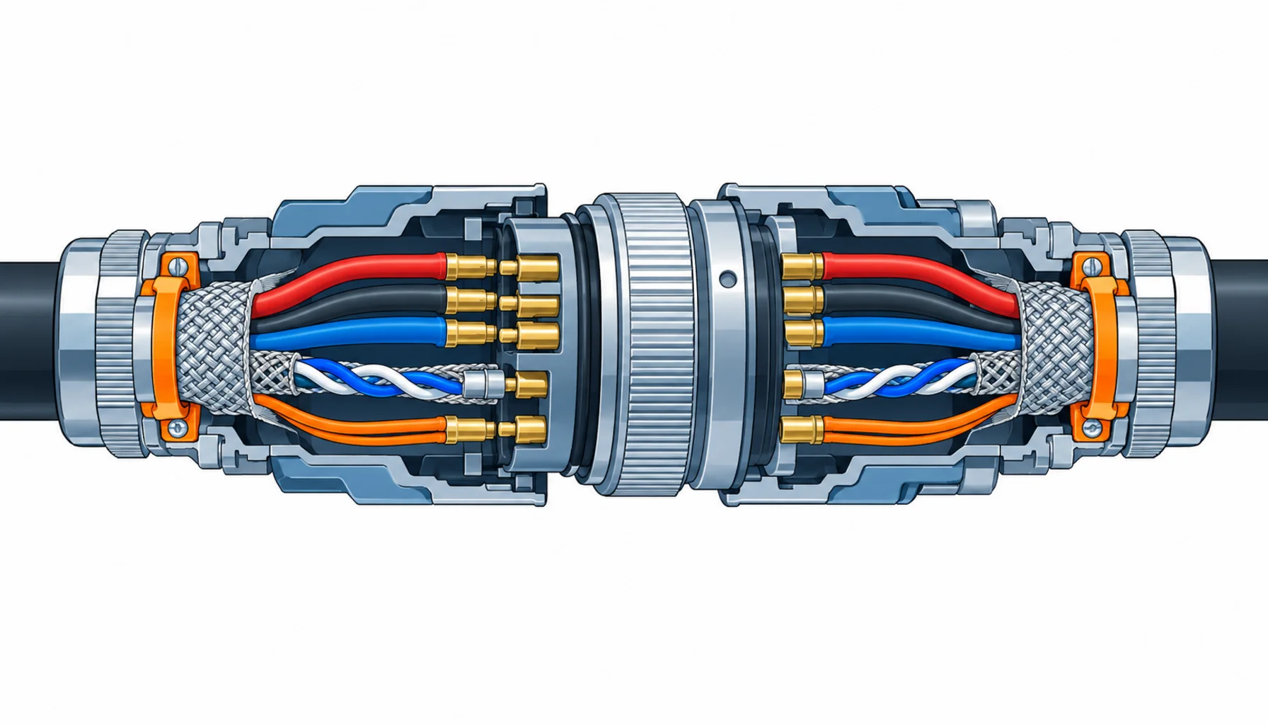
Quick Answer: On a servo axis, the connector is where three circuits meet: the power feed that drives the motor, the feedback loop that tells the drive where the motor is, and the brake circuit that holds it when power drops. The M23 circular family was built to carry all three through one mated pair, and it does the job well when the buyer specifies contacts, screening and strain relief as separate items with evidence for each. It fails quietly when one 16 A figure on a datasheet is taken as the whole specification.
Introduction
The servo cable and its encoder partner have been covered elsewhere as cables; our notes on servo cable construction and on encoder cable deal with what happens along the length. This guide starts where those notes stop: the mated interface, where the drive side housing meets the motor side flange and every conductor changes hands through a crimped contact. That interface concentrates the mechanical duty of the whole axis into a few square millimetres of contact, and most servo faults that look like tuning problems are actually interface problems.
The M23 family is the standard answer for this duty on mid-size axes, with smaller circular formats taking lighter circuits. What follows is the buyer’s version of the family: what each variant is for, which ratings actually decide field behaviour, and what evidence belongs in the RFQ.
The M23 Family, and Where It Sits
M23 is a 23 mm shell circular format carrying multipole power and screened signal contacts in configurable inserts. Three properties define it for servo work. Current: crimp contacts in the standard sizes carry servo power at ratings that derate with contact count. Screening: the shell and the insert support a 360-degree screen path from cable to housing, which the feedback circuit needs. Coupling: a threaded ring that survives vibration, where smaller snap-in formats do not.
The boundary lines matter when specifying. Below M23 sit the M12 families for sensors and light drives, covered in our note on buying M8 and M12 connectors; pushing servo power through them is the false economy described there. Above it sit the heavy-duty rectangular formats for cabinet and main feeds, covered in our note on heavy-duty rectangular connectors. The M23 lives between: axis-mounted, vibration-exposed, and handling the full servo circuit set in one shell.
The Decision Table: M23 Variants and What to Specify on Each
| Variant | What to Specify | Evidence to Demand | Cost and Lead-Time Driver | Where It Fails in Service |
|---|---|---|---|---|
| M23 power (servo feed) | Contact count and current per contact at the stated loaded-contact count, voltage class, crimp contact size against conductor cross-section | Derating table at the filled insert, temperature rise at rated load, mating cycle figure | Contact size and plating drive price; standard pin counts ship from stock | Hot contacts when the insert runs full load beyond the derating assumption |
| M23 hybrid (power + feedback) | Zone assignment on the insert, screened-pair assignment for the feedback section, segregation per the maker's layout | EMC evidence for the feedback section, crosstalk data between power and signal zones | One connector and one cable entry instead of two; savings show at installation, not on the part price | Encoder noise from power-side coupling where the zone assignment was ignored at assembly |
| M23 signal (feedback, encoder) | Pair assignment to twisted pairs, 360-degree screen termination at both ends, contact plating for low and stable resistance | Screen termination detail drawing, plating specification, insertion and withdrawal force data | Screened inserts and EMC couplings cost a step over standard signal formats | Position glitches traced to a screen that ends in a pigtail at the connector |
| Brake and holding circuits | Contact rating for the inductive brake load, contact protection concept, separate assignment away from feedback pairs | Switching data for inductive load, contact material declaration | Small contact count, low cost; the engineering is in the assignment, not the part | Chattering and contact erosion from unmanaged brake inrush, noise dumped into nearby pairs |
| Coupling and locking | Threaded coupling with stated tightening torque, vibration rating, keyway or clocking to prevent cross-mating of identical shells | Vibration test evidence, torque figure and torque mark practice | Quick-lock versions save assembly time but cost vibration margin on moving axes | Backed-off couplings on vibrating axes, cross-mated power and feedback inserts of the same size |
Contacts and Derating: The Rating That Actually Decides
The single most common procurement error in this family is ordering to the headline contact current. M23 contacts are rated per contact at a stated number of adjacent loaded contacts; a power insert running all contacts at full load derates substantially, and servo duty is exactly the full-load, fully-populated case. Ask for the derating table of the filled insert and specify against it, with a temperature rise figure at rated load as the evidence.
Contact technology is crimp, and it should stay crimp on anything that moves: the gas-tight joint survives vibration, and batch pull-off force records can evidence it. Plating follows duty, and our note on connector contact plating sets out the options; on servo power, state the plating explicitly, because a contact specified as “standard” is usually the thinnest tin the supplier ships.
The Feedback Interface: Where Servo Faults Actually Live
The feedback circuit is low-energy and high-consequence, which makes it the section worth over-specifying. Encoder signals travel as twisted, screened pairs, and the screen must arrive at the contact zone intact: a 360-degree clamp at the cable entry into the housing, continued through the insert design to the mating face. Where the screen stops as a pigtail, the axis works on the bench and glitches on the floor, usually in front of a customer. Our note on shielded connectors and EMC shows what the complete screen path looks like, and the insert schedule should name the screen termination per feedback pair rather than leave it to the assembler.
Hybrid inserts put power and feedback in one shell, and they are worth it: one mating operation, one cable entry, one spare part. The condition is discipline about the zone assignment the maker has already engineered; redistributing contacts in the field to suit a cable lay is how hybrid designs get their bad reputation.
Cable Entry and Strain Relief on a Moving Axis
The connector end of a servo cable sees every flex cycle the cable sees, concentrated at the gland. The gland clamping range must match the actual jacket diameter, the bend radius at the entry must respect the cable’s minimum figure, and the entry direction should follow the routing rather than fight it. Our note on the strain relief and connector interface covers the geometry, and the constructions that feed these connectors are in our note on drag chain cable. Where the entry is wrong, the failure signature is a broken conductor a short distance behind the connector, which reads as a cable fault and survives two connector replacements before anyone checks the gland.
What to Freeze Before the Order Goes Out
| Item | What to State | Evidence to Attach | Cost of Leaving It Open |
|---|---|---|---|
| Insert schedule | Contact count, current per contact at the stated loaded-contact count, assignment drawing per connector | An insert schedule with zone drawings | Configured inserts re-ordered at premium, and axes that cannot share spares |
| Derating basis | Current figures for the filled insert at full servo load | Derating table and temperature rise test | Hot contacts found two years in, on an insert that met the datasheet |
| Screen termination | 360-degree clamping per screened pair at both mating halves | Screen termination detail drawing per insert | Position glitches fixed with ferrites instead of the missing clamp |
| Plating | Plating named per contact class for power and feedback | Plating specification and thickness | Contact resistance drift on the feedback loop, read as an encoder fault |
| Termination method | Crimp on moving axes, named tooling and process | Batch pull-off force records | Intermittent joints that surface as drive tuning problems |
| Cable entry | Gland range matched to the actual jacket, entry direction per routing, bend radius at the entry | Gland data against the cable datasheet | Conductor breakage behind the connector, misread as a cable fault |
| Clocking and keying | Keyways preventing cross-mating where shells are identical | Clocking drawing per connector pair | A power insert mated to a feedback housing during commissioning |
| Mating cycles | Expected service and maintenance cycles stated for the coupling | Mating cycle test figure | Worn couplings on axes serviced monthly instead of yearly |
When an M23 Specification Is Not the Answer
Where the axis is small and the load is light. Sensor runs and small drives belong in the M8 and M12 families, where the sealed formats are cheaper and the mating is faster; the boundary cases are described in our M8 and M12 buying note.
Where the connector is really feeding a cabinet. Main feeds and multi-machine interfaces belong in the rectangular families; the decision logic is in our heavy-duty rectangular connector note.
Where the fault is behind the connector. An M23 replaced twice at the same axis is a symptom of a cable entry or routing problem, not a connector problem. Our note on why robot connectors fail lists the signatures worth checking before the third replacement.
Where dress pack routing takes over. On multi-axis arms the harness leaves the connector world early and becomes a dressed bundle; our note on robot dress pack cable covers where the interface responsibilities change hands.
RFQ Checklist
- Insert schedule with contact count, assignment drawing and current per contact at the stated loaded-contact count
- Derating table for each filled insert, with temperature rise evidence at rated load
- Screen termination method and detail drawing per feedback pair, at both mating halves
- Plating named per contact class, with thickness declaration
- Crimp termination on moving axes, with named tooling and batch pull-off force records
- Gland clamping range matched to the actual cable jacket, with entry direction and bend radius stated
- Clocking or keying defined where shells are identical, to prevent cross-mating
- Brake circuit contacts rated for the inductive load, assigned away from feedback pairs
- Mating cycle figure for the coupling, against the planned service interval
- Sample qualification protocol agreed with pass criteria before volume release
Conclusion
An M23 connector order is a system decision compressed into a part number. Specify the insert with its derating basis, the feedback section with its screen termination, and the cable entry with its clamping and radius, and the connector holds the axis together for the life of the machine. Take the datasheet headline figure instead, and the interface becomes the failure that reads as a servo problem for a month before anyone opens a hood.
Kexingyu Cable Group (KXYE) supplies the cable side of the servo circuit: the screened, twisted and continuous-flex constructions that terminate into M23 connectors on robot axes and machine tools, matched to the gland ranges and screen clamps of the families you standardise on. Send us the axis duty and the connector schedule, and we will return the constructions and sample lengths that fit; the fastest route is a request for quotation.


