
Buying Shielded Connectors for EMC: Why 360-Degree Termination Decides the Result
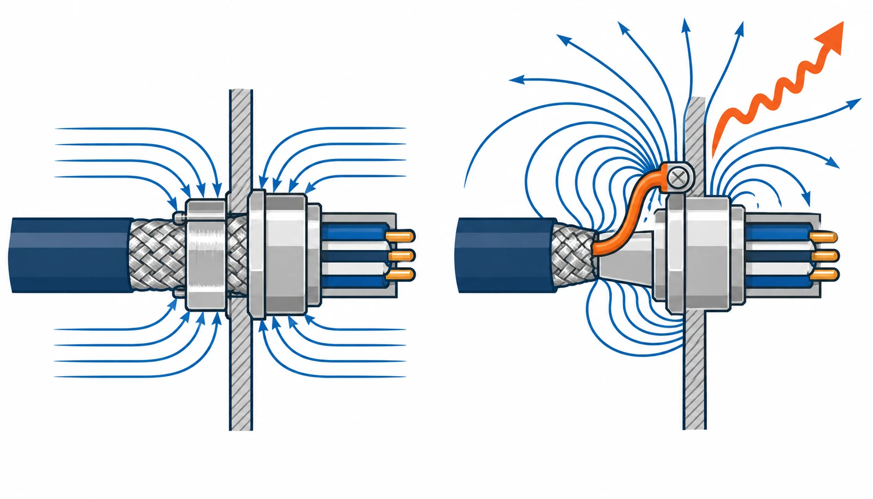
Quick Answer: A screened cable is only as good as the way its screen reaches the connector shell. Terminated around the full circumference, the screen keeps its low impedance and the shielding works at every frequency the drive produces. Terminated by a single drain wire, often called a pigtail, the screen becomes an inductor and its impedance rises with frequency exactly where it matters most, so a well-screened cable delivers almost nothing. The screen itself is usually fine; the interface is where the EMC is lost, and it is decided at order time, not at the bench.
Introduction
Buyers spend on screened cable and then lose the benefit at the connector, because a screen that is not bonded to the shell around its full circumference is a screen with a hole in it. The failure is easy to miss: the assembly passes a continuity check, the screen reads connected, and the machine still fails EMC, because the connection that was checked is a single wire that behaves like an antenna rather than a screen.
The harness overview in our note on robot harnesses and connectors places the screen among the other elements. This guide stays on the screened interface: what the screen needs at the shell, how each termination method performs, and what to write into the order so the weakest link is not the one you bought last.
What the Screen Does and Where It Stops Working
A screen does two jobs. It keeps external fields from coupling onto the conductors inside, and on a drive cable it returns the high-frequency current that the switching devices push into the cable’s own stray capacitance. Both jobs depend on the screen having a low-impedance path, and that path runs from the cable, through the connector, to the shell and the machine frame at both ends.
The place it stops working is the transition from cable to shell. If that transition has high impedance, the return current cannot flow freely, and the screen stops behaving as a screen and starts behaving as a radiator. The connector is therefore the part of the system that either completes the shield or breaks it, and how it does so is a specification decision rather than a cable one.
Why 360 Degrees Matters
A pigtail looks like a reasonable way to earth a screen: strip the braid, twist it into a wire, crimp it to a pin or a stud. Electrically it is the worst option, because a wire has inductance, and the impedance of an inductor rises with frequency. At the low frequencies of a continuity test the pigtail looks like a dead short. At the frequencies a modern drive produces, its impedance is high enough that the return current finds a different path, and the screen ceases to work.
A full-circumference bond does the opposite: it connects the screen to the shell over the whole perimeter, so the inductance is as low as the geometry allows and the impedance stays low across the range that matters. The difference between the two methods is not a matter of degree; it is the difference between a screened assembly and an unscreened one with a decorative braid.
The Decision Table: Screen Termination Methods and How Each Performs
| Method | EMC Effect | What to Specify | Evidence to Demand | Where It Fails in Service |
|---|---|---|---|---|
| Full-circumference clamp | Best practical option; low impedance across the frequency range | Clamp type and coverage, contact with the shell, and the tightening torque | A bond drawing plus transfer impedance evidence on the assembly | Clamp fitted over paint or contamination, so the bond is intermittent |
| Screen ring and ferrule | Very good; the screen is compressed between two metal parts over the perimeter | Ferrule size for the braid, compression method, and the shell material | A sectioned sample showing full braid contact | A ferrule sized for the wrong braid, leaving part of the screen unconnected |
| Shield spring | Good; suits small shells where space is tight | Spring material and plating, contact force, and the shell surface it bears on | A bond drawing and a mating cycle test | A spring that loses force and stops making reliable contact to the shell |
| Braid sleeve and clamp band | Good where the screen is a separate sleeve rather than a cable braid | Band coverage, overlap with the cable screen, and the bond to the shell | A fitted sample with the band closed to the specified force | An overlap that is too short, so the bond depends on how carefully it was fitted |
| Pigtail drain wire | Poor; high impedance at the frequencies that matter | Only as an addition to a proper bond, never as the bond itself | Transfer impedance measured on the finished assembly where used | The classic EMC failure: a screened assembly that screens nothing |
Coverage, Shell Bonding and the Mating Face
Three more numbers decide how well a screened assembly performs. The first is screen coverage, the percentage of the cable’s circumference the screen actually covers; optical coverage below the top of the range leaves a gap that leaks, and the figure belongs on the cable datasheet rather than in a general claim. The second is the bond from the shell to the machine, because the screen only works if it has somewhere to send the current; a connector bonded to a painted panel is not bonded at all. The third is the mating face, since the screen has to stay continuous across the joint: a pair that screens each half but not the interface between them is only as good as the interface, and that includes any shell-to-shell bond the design provides.
Where a cable carries power, screened signal and data together, the screening requirements differ by zone and the interface has to keep them apart as well as bonded, which is the design problem set out in our note on hybrid connectors. And on a moving axis, the grounding of a screened cable is complicated by the motion itself, which our note on EMC and grounding on moving cable covers.
What to Freeze Before the Order
| Item | What to State | Evidence to Attach | Cost of Leaving It Open |
|---|---|---|---|
| Termination method | Full-circumference bonding named for every screened entry, pigtail excluded | A bond drawing per connector family | A screened assembly that fails EMC and cannot be explained |
| Screen coverage | Optical or braid coverage stated as a percentage on the cable datasheet | The cable datasheet figure, not a general shielding claim | Gaps in the screen that leak at the frequencies the drive produces |
| Shell material and finish | Conductive shell surface at the bond, with any plating or paint stated | A surface specification and a first-article bond check | A clamp bonded to paint, giving intermittent contact |
| Shell-to-frame bond | How the shell is bonded to the machine, with the impedance path described | A bonding drawing and a continuity measurement on the frame | A screen with nowhere to send its current, so it radiates instead |
| Mating face bond | How the screen stays continuous across the mated joint | A drawing showing the shell-to-shell path at the interface | A screened pair that breaks the shield at the one place it must not |
| Bond torque and force | The torque or compression that makes the bond reliable, stated on the drawing | A first-article check at the specified torque | A bond that depends on how hard an assembler tightened it |
| Transfer impedance evidence | Transfer impedance or an equivalent EMC measurement for the assembly | A test report on the finished assembly, not the bare connector | No proof that the bonding actually performs across the frequency range |
| Assembly handling rules | What must not be done to the screen during assembly, such as cutting braid short | Workmanship notes and a first-article inspection | A screen trimmed too short at build, discovered only at system EMC test |
When Shielding Is Not the Answer
Where the geometry already separates the cables. Physical separation and route geometry remove more interference than a screen can, and paying for a screened assembly on a route that was never a problem is spend that returns nothing. The separation-first logic is the same one we set out for grounding on moving cable.
Where the cable screen is the wrong tool for the source. Filters and reference bonding deal with some interference that no screen can remove, and a shielded connector will not fix a drive whose own emission is being returned through a poor reference path. Fix the reference first, then decide whether screening is still needed.
Where the connector family never had a screen bond. Some families were never designed to carry a screen to the shell, and adding a pigtail to one of them produces the worst of both worlds. Family-level screening logic differs across the range, as our notes on M8 and M12 connectors, on heavy-duty rectangular connectors and on M23 and circular connectors for servo set out for each.
Where nobody has agreed what has to pass. Screening requirements belong to a system EMC plan, and buying a screened interface without one usually means paying for shielding that is either unnecessary or insufficient. The certification route and the evidence it needs are covered in our note on robot cable certification.
RFQ Checklist
- Full-circumference screen bonding named for every screened entry, with pigtail termination excluded
- Screen coverage stated as a percentage on the cable datasheet, with the figure written into the order
- Shell material and finish specified at the bond, with any paint or plating called out
- Shell-to-frame bond described, with a continuity measurement on the assembled machine
- Mating face bond shown on a drawing, so the shield stays continuous across the joint
- Bond torque or compression force stated, with a first-article check at that value
- Transfer impedance or equivalent EMC evidence required on the finished assembly
- Workmanship rules for the screen written down, including the minimum braid length at the bond
- Shielding judged against a system EMC plan rather than component by component
- Screen continuity checked after flex, where the assembly also has to survive motion
Conclusion
A shielded connector is not a part you can judge from its shielding claim or its continuity reading. What decides the result is whether the screen reaches the shell all the way around, whether the shell reaches the frame, and whether the bond survives the frequencies the machine actually produces. Buy the full-circumference bond, put the coverage figure and the bond torque into the order, and ask for transfer impedance evidence on the finished assembly rather than on the bare connector.
Kexingyu Cable Group (KXYE) supplies the screened cable side of these interfaces: the screened control and drive constructions whose braid coverage, drain arrangement and flex rating are chosen so a proper 360-degree bond has something to work with. Send us the EMC requirement, the routing and the connector schedule, and we will return constructions and sample lengths that fit; the fastest route is a request for quotation.


