Utility Tunnel Cable and Bridge Crossings: Routes, Fire Separation and What to Freeze
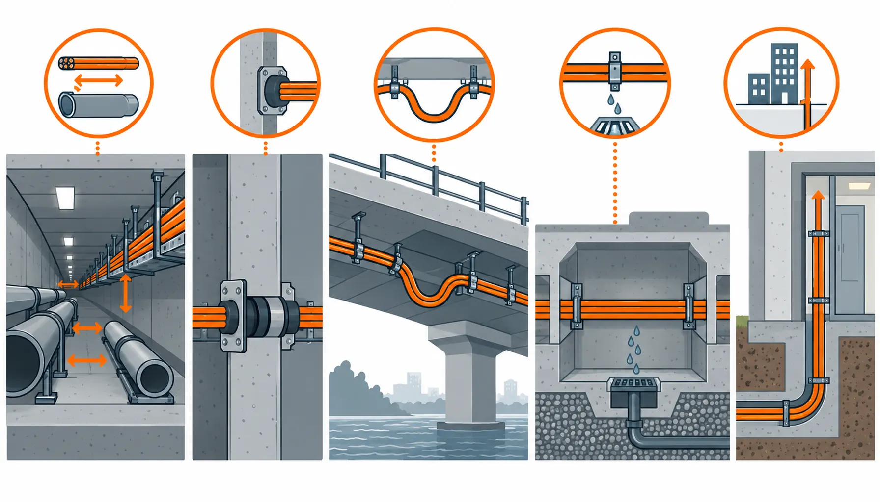
Quick Answer: Cable in a utility tunnel or on a bridge crossing is bought for the route rather than for the load. It shares a confined space with water, gas and heat services, it moves with the structure, it drains in ways that are hard to predict, and it is inspected rarely and repaired expensively. The specification therefore turns on four things: the fire separation between cable and other services, mechanical protection, water management, and the accommodation of movement at joints and expansion points.
Introduction
A utility tunnel is a structure that carries everything the city needs under one roof, and a bridge crossing is a structure that moves every day. Both are hostile to cable in ways that a building is not: access is difficult or impossible, the atmosphere is often wet or chemically aggressive, and the cable shares its corridor with services that are more dangerous than it is.
The cable package is therefore specified around the route, the separation and the maintenance regime rather than around an ampacity table. This guide covers the scopes, the fire separation question and the decisions to freeze before the order.
What Makes a Shared Route Different
Other services set the hazard. A utility tunnel usually carries water, sometimes gas, often heat distribution and sometimes telecoms. Gas is the one that changes the fire strategy: the tunnel becomes a space where an ignition source matters, and cable that can arc or burn is treated differently in a compartment that may contain a gas pipe.
Heat and condensation together. Heat mains and hot water pipes warm the tunnel, while cooler surfaces and unventilated ends condense moisture. That combination ages cable insulation faster than either condition alone, and it is a reason to specify the construction on temperature and moisture duty rather than on indoor general purpose.
The route is inaccessible. Cable on a bridge soffit or in a tunnel section between access points cannot be inspected, and a fault means scaffolding, a lane closure or a confined space entry. The cost of access dwarfs the cost of the cable, which argues for heavier mechanical protection and for spare capacity that reduces the need to return.
The structure moves. Bridges deflect, expand and contract, and tunnels built in sections settle. Cable crossing a movement joint or an expansion gap needs an arrangement that accommodates the movement instead of being stretched by it.
Utility Tunnel and Bridge Cable Scopes
| Scope | Duty | What to Specify | Evidence to Demand | Cost and Lead-Time Driver | How It Fails |
|---|---|---|---|---|---|
| Tunnel main run and cable gallery | Confined, warm, damp, shared with water and sometimes gas, rarely inspected | Construction for the ambient temperature and moisture, fire separation distance from other services, heat resistant where it runs close to heat mains | Temperature and moisture test data, separation drawing, construction declaration | The construction class and the supports; the cable metreage is a small part of the tunnel cost | Insulation aged by a combination of heat and condensation, found as a fault years later |
| Fire compartment boundary | Must hold the compartment across every cable crossing, in both normal and fire mode | The penetration as an approved system, with the cable construction and the seal tested together | System approval for the complete assembly plus installation records per boundary | The approved system and the labour to build it to the tested detail | A penetration approved as a sealant alone, failing the compartment requirement at inspection |
| Bridge deck and soffit crossing | Movement, vibration, weather, wind, occasional maintenance access from below | Armoured or ducted construction, support spacing for vibration, drainage at the lowest point, allowance for thermal expansion | Support schedule, drainage detail, armouring records, expansion allowance on the drawing | Access for installation; a bridge crossing is priced by the closure, not by the cable | Water standing in a duct that has no fall, or cable pulled tight across a joint and fatigued |
| Expansion joint and movement gap | The structure moves by a stated amount; the cable must follow without being stretched or pinched | An explicit movement allowance, a loop or a flexible arrangement, and a support detail that holds the cable while allowing the movement | Movement calculation from the structural engineer plus the detail drawing | Design time and the supports; the cable itself is unchanged | Conductors fatigued or a sheath cut at a joint after a few thermal cycles |
| Chambers, joint bays and risers | Concentrated joints and terminations, water collecting at the lowest point, difficult access | Sealed terminations, drainage below the cable, access and lighting provision, spare capacity for later circuits | Installation records per chamber, ingress rating at each termination, drainage detail | Access, lighting and drainage works rather than the cable | A joint bay that floods and takes out the circuits it was built to protect |
Fire Separation in a Shared Tunnel
The fire strategy of a utility tunnel is written around what else is in it. Three questions decide how the cable is treated.
Is there a gas pipe in the compartment? Where there is, the tunnel is designed on the assumption that an ignition source must be avoided and that a release has to be ventilated or contained. Cable then has to be contained, protected or separated so that it cannot become that ignition source, and the compartment boundary becomes a hard requirement rather than a convenience.
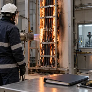
Can a cable fire spread along the tunnel? Cable in a vertical or inclined run acts as a chimney. Horizontal runs spread along the tray. The answer in most designs is a combination of cable construction with limited flame propagation and physical fire stops at intervals, so a fire cannot travel the length of the tunnel. Our notes on flame retardant cable categories and on LSZH versus fire retardant construction cover how the category is read and where smoke behaviour adds a second requirement.
Do any circuits have to keep working? Tunnel lighting, sump pumping, ventilation and the monitoring systems that detect a release may all be required to function during an incident. Those circuits are bought on circuit integrity at a stated grade and duration, tested on the installed assembly, and they are a different purchase from the class requirement on the rest. Our note on fire survival grades covers how the test conditions differ.
Every cable crossing the boundary needs a system. A penetration is approved as an assembly: the cable construction, the seal, the support either side of the wall and the installation method. Substituting a cable after approval invalidates the approval, which is one of the most common reasons a compartment fails at handover. Our note on firestop cable penetrations covers what the approved detail has to include.
Movement, Water and Access
Accommodate movement explicitly. Bridge decks and tunnel sections move, and the cable has to be given somewhere to go. A designed loop at each movement joint, or a flexible support arrangement, is normal; pulling the cable straight across the joint and relying on the sheath is not. Get the movement figure from the structural engineer and put it on the drawing with the detail. Our note on cable minimum bend radius is the constraint that decides how large the loop has to be.
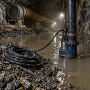
Design the drainage before the route. Utility tunnels and bridge ducts collect water at their lowest point, and the lowest point is usually where the joint bay is. Design the fall, the sump and the drainage rather than relying on the structure, and route the cable above the water line. Our note on flood risk and cable routes covers how the route should be designed against water.
Specify for the chemical and temperature environment. A utility tunnel that carries sewage or industrial drainage has a corrosive atmosphere, and one that carries heat mains runs warm. Both conditions argue against a general purpose construction. Our corrosion resistant cable for chemical and sewage environments page and the waterproof cable range cover the constructions used in both cases.
Pulls and supports in a confined space. Cable is pulled into a tunnel through chambers and around bends, often with limited access for a winch. Pulling tension and sidewall pressure at the bends are the two limits that decide whether the cable survives the installation; our note on cable pulling tension and sidewall pressure covers how they are checked. On a bridge, vibration means the support spacing is normally tighter than the minimum, and dynamic bracing at any point where the structure moves. Our note on seismic bracing for cable tray covers the hardware involved.
Plan for the access you will not have. Chambers should carry spare capacity, spare ways and a documented drawing updated after every change, because the next fault will be found from a drawing rather than from a look. Bonding records matter too: tunnel linings and reinforcement interact with the earthing system, and our note on grounding and bonding verification covers what to record at handover.
What to Freeze Before the Order
| Decision | What to State | Evidence to Attach | Cost of Leaving It Open |
|---|---|---|---|
| Fire separation from other services | The separation distance from gas, heat and water services, and where compartment boundaries sit | A separation drawing with boundaries marked | Trays re-routed, or a compartment requirement that cannot be met in the built tunnel |
| Penetration systems | The approved assembly at each boundary, tied to the cable construction supplied | System approval for the complete detail plus installation records | A compartment that fails inspection after the tunnel is closed up |
| Fire mode circuits | Which lighting, pumping, ventilation and monitoring circuits must keep running, at what grade | Survival test evidence with the standard and duration named | A tunnel safety system that cannot be demonstrated to the authority |
| Movement allowance | The movement figure at each joint, with the loop or flexible detail used to accommodate it | The structural movement calculation plus the detail drawing | Conductor fatigue or a cut sheath after the first few thermal cycles |
| Drainage and water management | The fall, the sump position, and the level the cable is set above the water line | A drainage drawing and the cable route shown relative to it | A flooded chamber that takes out the circuits and the joints inside it |
| Construction for the environment | Temperature rating and chemical resistance for the actual tunnel atmosphere | Ambient temperature statement and an atmosphere assessment where corrosion is a risk | Insulation ageing in a route that will not be inspected again for years |
| Spare capacity and records | Spare ways, spare ducts and a drawing that will be updated after every change | A capacity schedule and the as-built record | Every later circuit reopening a chamber and a boundary that was already sealed |
When a Heavy-Duty Specification Is Not the Answer
When separation is being bought as a substitute for a compartment. Extra distance reduces fire risk but does not replace a boundary. Where the strategy calls for compartmentation, distance is not an alternative and buying it instead leaves the requirement unmet.
When armouring is being used to avoid a proper support arrangement. Armour resists mechanical damage; it does not carry the cable. A route that needs better supports is not fixed by a heavier sheath.
When the movement allowance is being left to the installer. Pulling cable tight across a bridge joint looks correct on the day and causes fatigue after a few temperature cycles. The allowance has to be designed, dimensioned and drawn.
When a fire rated construction is specified across the whole tunnel. Only the circuits the safety strategy names need survival performance. Paying the grade premium along the whole route is a large avoidable cost, and the money is better spent on separation and on the penetrations.
RFQ Checklist
- Separation distances from gas, water and heat services, with boundaries marked
- Approved penetration systems listed by boundary, tied to the construction supplied
- Circuits required in fire mode, with survival grade, duration and the standard
- Ambient temperature and chemical exposure along each section of the route
- Movement figure at every joint or expansion gap, with the accommodating detail
- Drainage fall, sump positions and the level the cable is set at
- Construction for moisture and corrosion, with gland and termination type
- Support spacing for vibration, and dynamic bracing at movement points
- Pull lengths, access positions and the pulling tension limit for each section
- Spare ways, spare ducts and the as-built record to be maintained
- Bonding and earthing records required at handover
Conclusion
Cable in a shared route is specified by what surrounds it. Decide the fire separation and the compartment boundaries before the tray layout is drawn, buy the penetrations as assemblies tied to the cable you are actually supplying, design the movement allowance and the drainage rather than leaving them to site, and choose the construction for the real temperature and atmosphere. Then keep spare capacity and an up-to-date drawing in every chamber, because the next fault will be found from paperwork rather than from a look.
Kexingyu Cable Group (KXYE) has manufactured cable in Quanzhou since 1996, supplying armoured, fire-rated, water resistant and corrosion resistant constructions for infrastructure work, with the test records and construction declarations that a compartment approval depends on. Send us the route drawing, the separation requirements and the movement figures, and we will come back with the constructions, the evidence for each boundary and the supports for the route. A request for quotation is the fastest route.