Cable Vibration Fatigue on Site: Supports, Spacing and What to Specify
Quick Answer: Vibration fatigue is a cycle-count problem. A cable fails from vibration when a small movement repeats millions of times at a point that should have been restrained, so the first fix is usually the support arrangement rather than a different cable. Where the cable genuinely has to move, the conductor class, the stranding and the screen construction matter, and all three have to be specified against a cycle count and a radius instead of bought on the word flexible.
Introduction
Vibration is the quietest way to destroy a cable. There is no impact, no water and no chemical, just a movement of a fraction of a millimetre that repeats for years at a restraint or a terminal until a strand work-hardens and breaks inside insulation that still looks new.
This guide is for the buyer specifying cable where machines, transformers, compressors or traffic keep the steelwork moving. It covers how fatigue actually works, where vibration reaches a cable, the support and conductor measures that answer it, and the decisions to freeze before the order goes out. The flex side of the problem is in our note on cable flex testing methods, and the support side is close to the reasoning in our note on seismic bracing for cable tray.
How Vibration Fatigue Actually Works
It is a cycle count, not a load. Fatigue depends on how many times a stress is applied, not on how large it is. A movement too small to see can break a conductor if it happens often enough, which is why a cable that only ever sees a gentle hum can still fail at a termination.
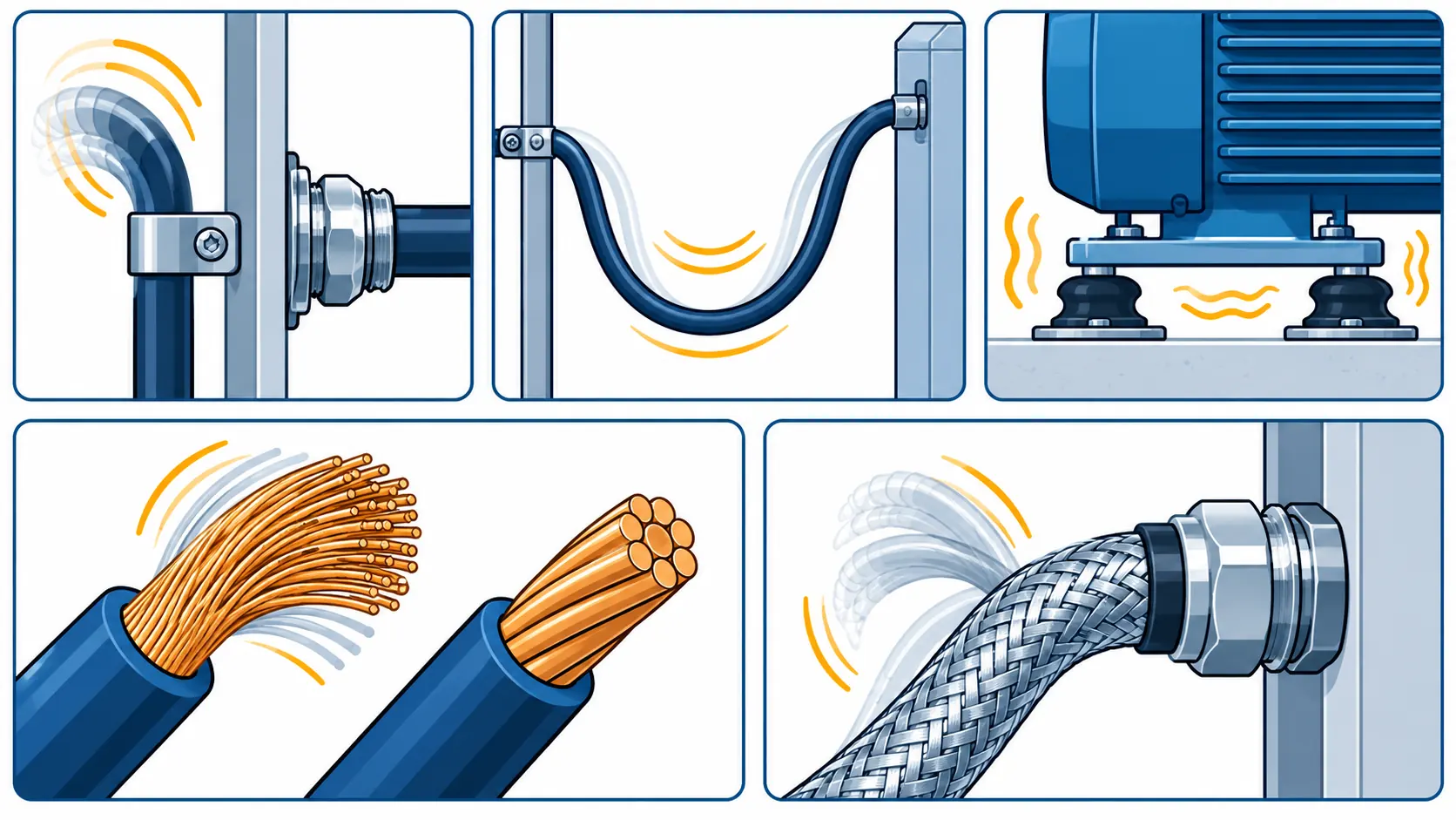
Stress concentrates where movement is restrained. A cable that is free along its length and clamped at one point bends repeatedly at the edge of the clamp. The clamp is doing its job, and the cable is failing at the worst possible place because the movement all happens in one short length.
Radius multiplies the effect. Flex life is a steep curve rather than a number: halving the bend radius reduces the cycles the cable can take by an order of magnitude or more. That is why a vibration failure is often a radius problem that shows up as a fatigue problem.
Strands fret against each other. Inside a stranded conductor the individual wires rub where the cable flexes, and fretting removes metal and starts a crack. The damage is invisible from outside and is only found at the point where the strand finally breaks.
Terminals take the last hit. Where a cable is bolted to a busbar or a machine terminal, vibration works the joint, and a loose terminal heats and then fails. Terminal fatigue and conductor fatigue usually appear together on the same machine.
Where Vibration Reaches a Cable
The last metres to a machine. Between a fixed tray and a motor or a pump terminal box, the cable bridges a moving machine and a static structure, and that bridging length sees every cycle the machine produces.
Transformer, reactor and busbar areas. Magnetic forces keep steelwork humming at twice the supply frequency, and cables cleated to that steelwork are shaken continuously. Our note on transformer noise and vibration mitigation covers the source side of the same problem.
Support and Damping Options Compared
The table sets out the measures a buyer can actually specify: what each one does, what to write into the requisition, the evidence to demand, what drives cost and lead time, and how each one fails when it is applied on its own.
| Measure | What it does | What to Specify | Evidence to Demand | Cost and Lead-Time Driver | How It Fails |
|---|---|---|---|---|---|
| Restraint and cleat spacing | Stops movement happening at the cable's weakest point by controlling where it is free | Cleat type, spacing along the route, and where movement is deliberately allowed | A support arrangement drawing accepted before installation, plus the cleat load rating | Almost no material cost; the cost is design and inspection time | Cleats fitted at even spacing with no thought to the machine, so all the movement lands at the gland |
| Flexible tail at the machine | Absorbs the relative movement between a vibrating machine and a fixed route | Tail length, the movement it must absorb, and the bend radius at each end | Flex data at the declared radius, plus the gland and strain relief arrangement | Fine stranding costs more; factory-fitted tails add days to the lead time | A flexible tail clamped at both ends, so it has nowhere to move and fails at the ferrule |
| Damping and isolation | Reduces the amplitude reaching the cable rather than making the cable stronger | The mount type and its rated frequency, and which items are isolated from the steelwork | Mount specification with its frequency range, and a vibration survey after installation | Accessory cost is modest; the survey and the re-work if the mount is wrong are not | A mount tuned to the wrong frequency, which amplifies the vibration instead of reducing it |
| Flexible conductor and stranding | Lets the conductor survive the cycles that the support arrangement cannot remove | Conductor class, strand count, nominal strand diameter and the lay of the strands | A flex result at the service radius and cycle count, plus the construction sheet | Stranding and the extra drawing passes add both cost and lead time | A general flexible cable bought where a continuous-flex construction was needed |
| Screen and armour construction | Keeps the screening or the mechanical layer from breaking before the cores do | Screen type, its coverage and how it is terminated, plus any armour fitted | Screen flex results and the termination method for the screen at each end | Braid and foil constructions differ in both price and flex life | A foil screen that cracks at the first significant movement and loses its EMC function |
Conductor, Screen and Armour Under Vibration
Conductor class sets the ceiling, not the answer. Class 5 and class 6 conductors tolerate far more cycles than class 2, but the class sets a maximum strand diameter rather than a fixed build. Two cables both called flexible can differ substantially, so ask for strand count and nominal strand diameter at the sizes quoted. The class system is set out in our note on IEC 60228 conductor classes.
Rope-laid strands outlast bunched ones. Where a conductor is built up in layers with a controlled lay, it distributes the movement instead of concentrating it, and the gain in flex life is bigger than the gain from one class step. Our note on class 6 conductor flex covers where the construction detail matters more than the class number.
Screens break before cores do. A foil screen has almost no flex life and cracks early; a braided screen survives longer but loses coverage if it is strained. Specify the screen type against the movement and confirm how it is terminated, because a screen that breaks at the gland is the classic EMC failure.
What to Freeze Before the Order Goes Out
Six decisions decide whether a vibration-duty order can be defended. All are cheap on a specification sheet and expensive once a machine is running.
| Decision | What to State | Evidence to Attach | Cost of Leaving It Open |
|---|---|---|---|
| Movement and frequency | The amplitude and frequency at each machine, and whether the movement is continuous or intermittent | A vibration survey at the machine, or the manufacturer's figure where one exists | A cable bought for the wrong duty, either over-flexible or not flexible enough |
| Where movement is allowed | The free length, the restraint points and the radius at each of them | A support arrangement drawing showing where the cable is free and where it is held | Every cycle concentrated at the gland, which is where the cable then fails |
| Conductor class and stranding | Class, strand count and nominal strand diameter for the sizes ordered | A flex result at the service radius and cycle count, with the construction sheet | An intermittent earth fault that is almost impossible to find |
| Screen type and termination | Foil or braid, coverage, and the termination arrangement at both ends | Screen flex evidence and the termination method for the screen | A cracked screen and an EMC problem that arrives with the drive |
| Damping and isolation | Whether the machine or the structure is isolated, and the mount frequency range | Mount specification and a post-installation vibration reading | A mount that amplifies vibration, and a cable that fails faster than before |
| Terminal integrity | The torque values, the anti-vibration hardware and the re-torque interval | A torque schedule issued with the delivery and recorded at commissioning | A loose terminal that heats and fails, blamed on the cable |
Installation: Spacing, Damping and Slack
Support close to the source, not evenly spaced. A cleat near the machine reduces the free length that vibrates, which is the opposite of the intuition that a cable should be left loose. Let the movement happen in a length that was designed for it rather than in the last few centimetres before a gland.
Leave a service loop that has somewhere to go. A generous loop absorbs movement, but only if it is not clamped flat against a wall or pinched between two cleats. The loop has to be able to open and close, and its radius is part of the specification.
Do not clamp at the gland. The classic vibration failure is a cleat fitted hard against a gland neck, which transfers every cycle into the termination. Leave the cable free behind the gland and support it further back.
Use the right cleat material. A hard cleat edge wears the sheath where a softer or radiused one does not, and the abrasion and the fatigue then arrive together. The materials and the wear patterns are covered in our note on cable damage wear patterns.
Incoming Inspection and Field Diagnostics
Ask for flex evidence, not a datasheet adjective. What counts is a flex or torsion result quoted at a radius and a cycle count, on the construction delivered. A cable described as high-flex without figures is a claim rather than a specification.
Count the strands on a sample. Strand count and nominal strand diameter can be checked in ten minutes on a cut sample, and they are the two figures most often substituted. Where the duty is severe, that check is worth doing at goods-in rather than at commissioning.
Watch for an intermittent earth. Strand fatigue usually announces itself as a fault that appears when the machine runs and disappears when it stops. Tracking it early is far cheaper than waiting for a hard failure, and the routine checks are in our note on in-service cable testing.
Cost and Lead Time
Support and clamping changes cost almost nothing and fix most vibration problems, which is why they belong first in the sequence. Flexible conductor and rope-laid constructions add cost and some lead time, because drawing and stranding take longer on finer wire. Factory-fitted flexible tails and moulded assemblies are the longest item and normally run to order, so they need to be in the programme early.
Copper is the largest element of the price and the stranding premium is small beside it, but over a project that runs a year the movement in copper is usually the bigger number. Ask how the copper element is calculated and how long the price holds; the mechanism is covered in our note on copper price and cable procurement.
When a Stiffer Cable Is Not the Answer
When the failure is at a restraint. A break at the edge of a cleat is a support problem. A more flexible cable moves the failure a few months later unless the restraint is changed.
When the machine is out of balance or misaligned. Vibration is often a symptom of a machine fault, and absorbing it in the cable adds a consumable cost to a fault that belongs at the coupling or the mounting.
When a flexible tail hides an alignment error. A flexible connection absorbs normal movement, not a machine installed out of line. Using it that way turns a commissioning fault into a permanent wear item.
When the structure is resonating. Where the support steelwork vibrates at the machine frequency, the fix is a mount or a brace, not a cable. Buying a more flexible construction into a resonant structure only delays the failure.
RFQ Checklist
- The movement at each machine, with its frequency and amplitude, taken from a survey or the maker’s data
- Where the cable is held and where it is free, shown on a support arrangement drawing
- Conductor class, strand count and nominal strand diameter at the sizes ordered
- Whether the strands are bunched or rope-laid, and the flex result at the service radius
- Screen type, coverage and the termination arrangement at both ends
- Armour or no armour, and the bend radius that follows from that choice
- Cleat type and material, with the spacing at and near the machine
- Damping or isolation for the machine and the structure, with the mount frequency range
- Terminal hardware, torque values and the re-torque interval
- Factory-fitted tails or moulded ends, with the working lengths and drum schedule
- Flex and torsion tests to be witnessed, with records that travel with the drums
- Copper basis and the validity window of the quoted price
Conclusion
Vibration fatigue is decided by where the movement happens rather than by how flexible the cable is. Control the restraint points, keep the movement in a length that has a radius and a cycle count behind it, and use flexible conductor only where the support arrangement cannot remove the cycles. The cable is the last line of defence here, and on most sites it never has to be the first.
Kexingyu Cable Group (KXYE) has manufactured cable in Quanzhou since 1996, including flexible and continuous-flex constructions with rope-laid conductors for machine connections, transformer areas and long site runs, with flex data that names the radius and the cycle count. Send us the machine list with the movement and the support arrangement, and we will come back with the conductor build, the screen and the tests that apply. A request for quotation is the fastest route.