
AGV and AMR Cable Requirements: Power, Signal and Charging
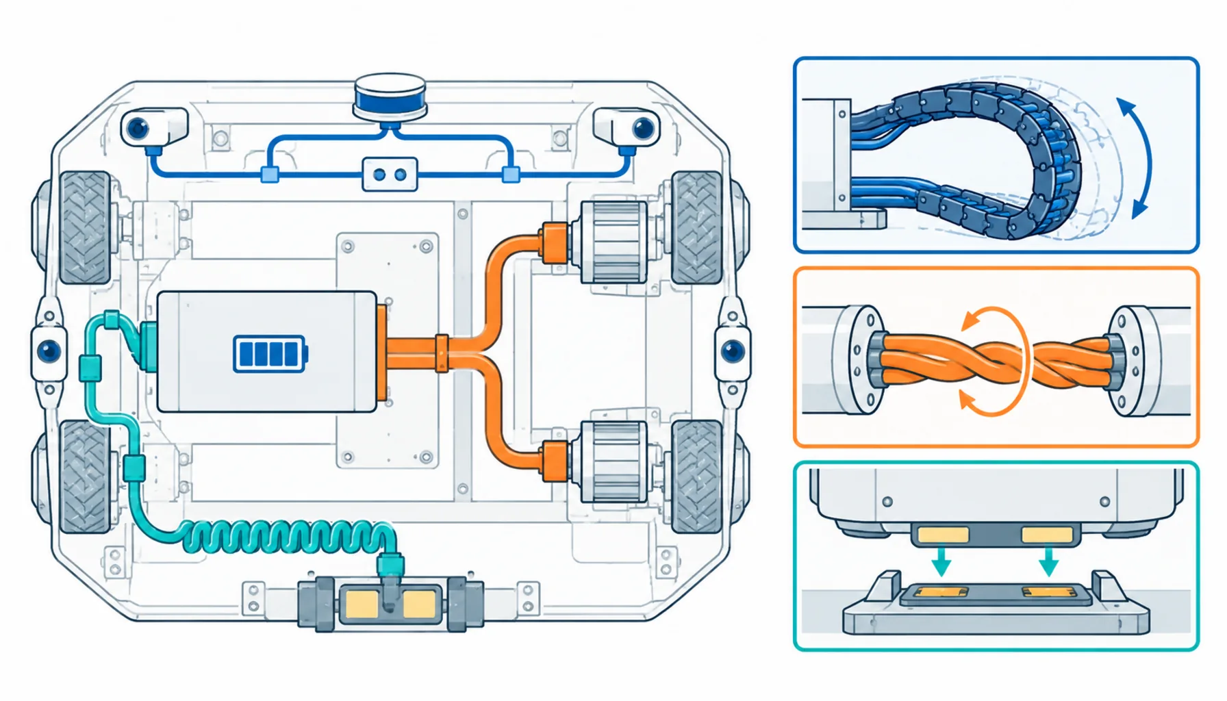
Quick Answer: An AGV or AMR needs three cable jobs done at once — battery power, encoder and safety signals, and charging — each flexing and twisting in a chassis that never stops moving.
Warehouse automation has quietly become one of the largest consumers of motion cable in the world. Autonomous mobile robots alone are projected to grow from roughly $7.6 billion in 2024 toward more than $23 billion by the early 2030s, and every one of those vehicles carries a wiring loom that flexes with every steering correction, twists with every rotation on the spot, and plugs into a charger dozens of times a day. When an AGV goes down, the aisle it blocks goes down with it — so the cable inside these machines is not a commodity purchase. It is uptime insurance. This guide breaks down what each cable family on a mobile robot actually has to survive, where standard cabling falls short, and the specification checks that keep a fleet running instead of rotating through repair bay visits.
Introduction
AGV and AMR platforms compress a control cabinet, a drive system and a charging station into a box the size of a pallet — and then drive it around for sixteen hours a day. There is no static wiring in that box. The steer assembly flexes its harness through millions of small movements. The drive wheels put torsion into the power feeds every time the chassis pivots. The battery leads see high current with sharp ripple content from the motor controller. The safety scanner loops, the lift mast harnesses rise and fold, and the charging contacts deliver full current hundreds of times a day. A mobile robot is, electrically speaking, a bundle of power and signal circuits packed into the smallest possible volume and then asked to move.
That combination — high current, sensitive signals, tight space, constant motion — is exactly the set of conditions where cable choice decides fleet economics. A warehouse operator buying fifty robots is really buying fifty wiring harnesses with wheels attached. The failure data behind common cable failure causes reads differently when the cable in question is driving itself around a distribution center: conductor fatigue shows up as a vehicle that limps home to the charger and never leaves it, and shield damage shows up as an intermittent navigation fault that no firmware update will fix.
The Three Cable Jobs on a Mobile Robot
Every AGV and AMR, from a 200 kg tote mover to a 3,000 kg pallet shuttle, runs the same three electrical jobs, and each has its own motion profile and failure modes. It pays to specify them as three separate problems rather than one harness quote.
| Cable Family | What It Does on the Vehicle | Motion and Environment It Must Survive | Typical Failure in Cheap Versions |
|---|---|---|---|
| Battery and drive power | Carries high DC current from battery to motor controllers and lift hydraulics | Torsion at steer pivots; vibration; heat soak near controllers; ripple currents | Strand fatigue at gland transitions; insulation creep where harness crosses the suspension |
| Signal and safety | LiDAR and camera feeds, encoder lines, safety loop, lift and light curtains | Continuous small flexing at sensor mounts; EMI from drive electronics a few centimeters away | Shield braid rupture — navigation drops out and returns, the worst kind of intermittent fault |
| Charging | Feeds contact rails, opportunity chargers or automatic docking connectors | Coiling and uncoiling at every dock; contact force; current spikes at plug-in | Jacket cracking at the coil memory point; conductor damage from arcing at worn contacts |
Power Cabling: Battery Current Is Not Gentle Current
The first instinct on a mobile platform is to size battery leads from the average load. That instinct is wrong. Drive controllers draw in sharp pulses, and regenerative braking pushes current back into the pack with the same sharpness. The cable therefore lives with thermal cycling and electromagnetic ripple, not a flat DC trickle. Conductors need real sizing headroom — the same discipline behind voltage drop and ampacity sizing — and the insulation system has to tolerate the heat a controller dissipates into the compartment during a full shift.
Motion is the second half of the problem. A differential-drive AGV twists its own power feeds every time it corrects heading; a turret-steered vehicle does it thousands of times an hour. Stranded Class 6 conductors with short lay lengths hold up where coarse-stranded automotive-style cable work-hardens and snaps, usually within the first centimeter of the gland where bending concentrates. Harness routing matters as much as construction: a power feed lashed tight across the suspension will fail no matter what the datasheet promises, because it is being flexed through a radius the cable was never rated for.
Signal Cabling: Navigation Lives and Dies on Shield Integrity
A mobile robot is a hostile electromagnetic neighborhood. Motor controllers switch kilowatts a few centimeters from the safety scanner’s signal harness; battery cables carry ripple past encoder lines; wireless radios sit inside the same enclosure. The signal cables that feed navigation sensors and safety loops are low-energy and noise-sensitive, which makes shield construction the whole game. A braid shield that survives constant small flexing keeps the safety loop and the localization data clean; a foil shield cracks after weeks of vibration and hands the maintenance team a ghost — a vehicle that hesitates at one specific corner of the facility, faults, and then passes every bench test.
Separation discipline carries over from fixed installations: power and signal runs want physical distance or a barrier inside the chassis, and the single-point grounding habits described for control circuits apply here with even more force, because the vehicle ground plane is small and everything on it shares the same return. Fleets that treat signal harnesses as an afterthought spend their integration budget chasing noise instead of commissioning routes.
Charging Cabling: Hundreds of Cycles a Day, Every Day
Opportunity charging changed the duty profile of the charging circuit. Older fleets charged overnight; modern fleets top up at every dock for ninety seconds at a time, which means the charging cable and its connectors complete several hundred charge cycles per vehicle per day. The cable itself often lives as a service coil — wound and unwound at every docking, flexed at the same memory point thousands of times a week. Fine-stranded, high-flex construction with a jacket compound that resists the set memory of coiling is the difference between a charging harness that lasts the vehicle’s life and one that cracks open at the coil within a year.
The electrical side deserves equal respect. Charging current at plug-in is not smooth — contact resistance, misalignment and controller ramps create spikes and localized heating at the contacts. Chemistry choices in the battery room shape this too; the charge profiles behind LiFePO4 and other battery chemistries differ in current curves, and the charging harness has to be specified for the fleet’s actual charge strategy, not a generic one. Safety loops through the charging circuit — interlocks, ground-fault detection, contact status — ride the same loom and deserve motion-grade construction as well, because a safety cable that fails intermittently is worse than one that fails loudly.
What Actually Fails in the Field
Fleet maintenance records converge on a short list. Conductor fatigue at gland entries and suspension crossings leads the list, and it is a routing and strain-relief problem before it is a cable problem. Shield braid rupture on sensor harnesses comes next, usually presenting as intermittent navigation or safety faults. Jacket damage from the operating environment — debris in the aisle, dock edges, the vehicle’s own suspension travel — accounts for much of the rest. Notably absent from the list is the failure mode buyers spend the most time worrying about in quotations: conductor ampacity. The copper is almost never the problem. The motion engineering around it is, and the site-level wiring that feeds the fleet’s charging lanes has its own parallel requirements covered in industrial power distribution planning.
| Check | What to Pin Down | Why It Decides the Outcome |
|---|---|---|
| Duty profile | Hours per day, docks per shift, steering corrections per hour | Sets flex life targets for every harness on the vehicle |
| Power loads | Peak drive current, regen pulses, lift inrush, cable run lengths | Battery leads sized on averages cook at peak |
| Signal inventory | Scanner, camera, encoder and safety circuits with their EMC needs | Shield and separation decisions are made here, not debugged later |
| Charging strategy | Opportunity or overnight, current, cycles per day, dock geometry | Charging harness duty varies by an order of magnitude between strategies |
| Routing map | Every point where a harness bends, twists or crosses the suspension | Failures concentrate at routing constraints, not mid-run |
| Environment | Cold stores, washdown zones, debris, dock edges, UV at outbound lanes | Jacket compound is chosen by the facility, not the catalog |
| Spares and proof | Flex test data, batch traceability, pre-terminated spare looms | A failed vehicle is measured in blocked aisles, not meters of cable |
When Mobile Robot Cabling Rules Are Not the Answer
Honesty about scope keeps this guide useful. The requirements here are written for vehicles that carry their own cable — AGVs, AMRs, tugger and forklift platforms. They do not transfer directly to infrastructure-side cabling: the fixed wiring from charging lane to power distribution belongs to stationary installation practice, and the cable feeding a conveyor or an automated storage and retrieval system follows the machinery rules of guided motion rather than vehicle harness rules. Whole-facility power engineering around a fleet is its own discipline, and the grounding, protection and redundancy decisions behind distribution design should come from the electrical engineer of record, not the vehicle datasheet. Know which side of the charger each cable sits on before you specify it.
RFQ Checklist: What to Send the Cable Supplier
Put the fleet’s real duty in writing before quotes come back:
- Vehicle class and duty: hours per day, charge cycles per shift, steering and lift movements per hour
- Power circuit data: peak and continuous current, voltage, regen behavior, run lengths in the chassis
- Signal inventory: scanner, camera, encoder and safety circuits with separation requirements
- Charging method: contact or dock type, current profile at plug-in, cycles per day
- Facility environment: temperature band, debris, washdown zones, dock edge contact points
- Required flex life per harness family, with the test method that will verify it
- Spares policy: pre-terminated looms, batch traceability and lead time for replacement sets
Conclusion
An AGV or AMR asks one wiring system to do three hard jobs at once — move kilowatts, carry clean signals through a noisy chassis, and survive hundreds of charging cycles a day — all inside a box that never stops flexing. Fleets that specify each cable family against its actual motion and duty profile get vehicles that age gracefully; fleets that buy one generic harness get to learn the failure list from the maintenance log instead.
Kexingyu Cable Group (KXYE) supports mobile robot builders and fleet operators with motion-grade constructions for power, signal and charging circuits, batch traceability and honest duty ratings. Send us your vehicle duty profile and charging strategy through the RFQ page, and we will respond with constructions matched to each circuit rather than one quote for all of them.


