
Buying Drone Charging Cable for Ground Support: What to Specify at the Pad
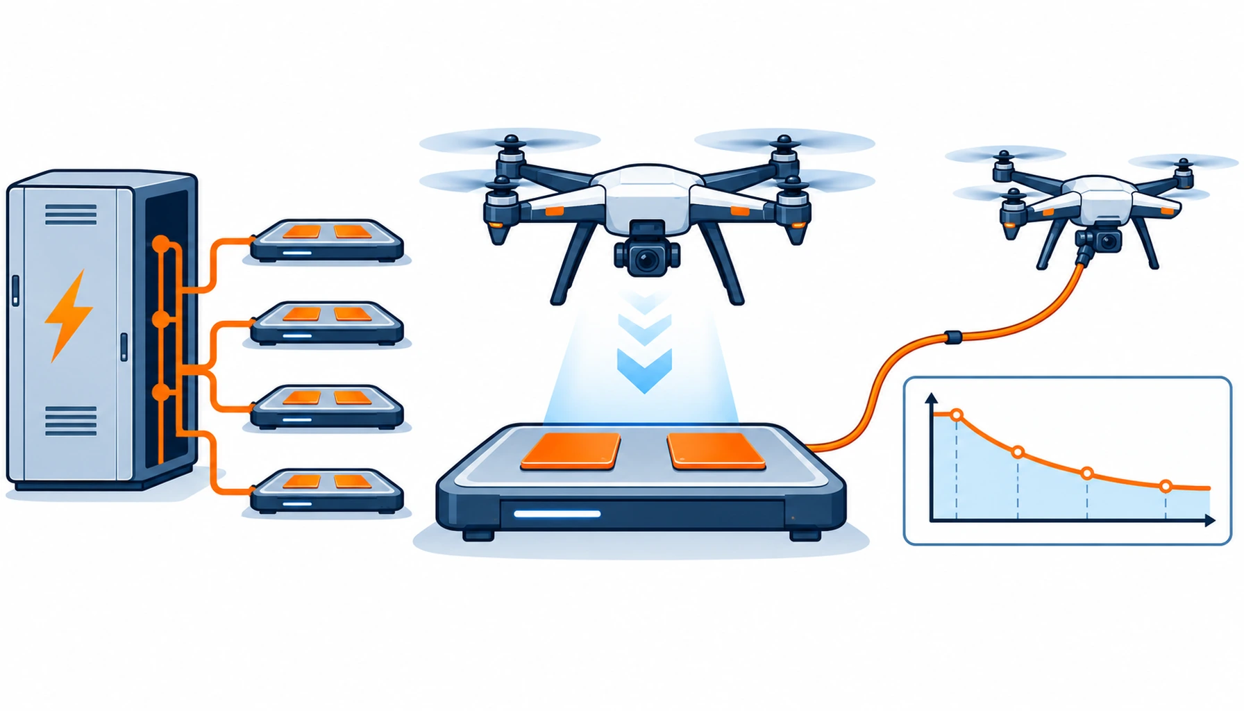
Quick Answer: The cabling at a drone pad is usually the last item specified and the first item to ground the fleet. It has to carry a high direct current in short bursts, survive hundreds of mating cycles, sit outdoors in whatever the weather does, and resist being dragged by ground crew. Five figures decide the purchase: charge current, mating cycles, contact alignment tolerance, ingress at the mated state, and the pad abrasion the cable will see.
Introduction
Drone operations have moved from a single aircraft and a field to multi-bay pads, rooftop stations and automated hangars, and the electrical work at those sites is closer to a small charging station than to a robot installation. The machines are airborne; the cable is not, and it is the part with the least attention and the most handling.
Contact charging on a ground vehicle is a related problem and is covered in our note on AGV charging cable. What follows is specific to a drone pad, where the aircraft lands onto a fixed interface rather than driving onto one.
Charging at a Pad Is a Burst Duty, Not a Continuous One
Drone packs are charged between short flights, so the profile is a high current for a short period, several times a day, rather than a long trickle. That pattern loads conductors and terminations differently from continuous charging: the cable spends most of its life at ambient and then heats quickly, and every cycle ends with a cooling period in which condensation can form inside a cabinet that has just been warm.
Declare the current, the duration and the number of charges per day, and ask for a temperature rise record at that burst rather than a continuous rating. Conductor size for the same nominal current can differ substantially between a continuous and a burst duty, and buying the continuous figure usually means buying copper that is never used.
Where the pad charges several aircraft at once, the current in the cabinet feeder is not the sum of the bay currents. Diversity matters, and it should be stated rather than assumed, because a feeder sized on the sum of every bay is a common and expensive over-buy. The general reasoning about current and conductor sizing carries over from our note on robot battery cable.
Contact Wear and the Alignment Problem
A contact charging pad has no connector to plug in, and that is where the engineering moves. The aircraft lands within a tolerance, the contacts meet, and the current passes through two surfaces that are not clamped together the way a plug is. Every landing produces a small relative movement and a small arc, and both attack the contact surface.
Two specification items follow. The first is plating: a harder, thicker contact surface survives repeated make-and-break far longer, and what each option buys is set out in our note on connector contact plating. The second is the alignment tolerance itself, which the pad designer sets and which the buyer should write down, because a pad that demands millimetre accuracy will spend its life failing to charge rather than failing to conduct.
A plug-in bay avoids the alignment problem and creates a different one. Somebody has to plug the cable in, hundreds of times a day in a busy operation, which makes mating cycle count the governing figure and pushes the choice toward a connector rated for it. Count the cycles before choosing between the two approaches, because the arithmetic is not close either way.
Weather, Dragging and the Pad as an Abrasive Surface
A pad is an outdoor surface in most operations, and its cable is exposed to ultraviolet, rain, standing water and, in winter, salt or grit carried in by the aircraft and by people. The exposure is close to that of any outdoor robot, and the constructions built for it are gathered under the weather resistant cable range.
The pad is also abrasive. Concrete, composite decking and anti-slip coatings grind a cable that is dragged across them, and ground crew do drag cables, particularly where a cabinet is mounted at the pad edge and the run crosses the landing area. Armouring the crossing sections as replaceable pieces is cheaper than upgrading the whole run, and it also protects the cable from being kinked around the corner of a cabinet.
Where a cable leaves a fixed cabinet and becomes free, it must be supported. An unsupported length hanging from a gland is loaded by every movement it sees, and the transition is where most pad-side failures begin. The mechanics of that transition are the same ones described in our note on cable minimum bend radius.
Reeling, Tethers and the Other Two Duties at a Pad
Not every cable at a pad is a charging cable, and the two other duties deserve separate specifications. A tethered drone drawing power through a cable for long endurance is a continuous supply problem, with voltage drop over a long length as the governing figure and the tether itself as a handling item to be coiled, unreeled and protected from the same abrasion as everything else on the pad.
A trailing or reeling arrangement, where the cable follows the aircraft or a ground unit, needs a construction rated for reeling rather than for static installation. Products such as the reeling cable family exist for exactly that duty, and a composite reel cable such as the network composite reel cable is the usual answer where power and data travel together.
Where the site also runs ground vehicles with their own pads, buying the two interfaces from one specification usually costs more than it saves. A ground vehicle drives onto its interface and a drone lands onto one, and the two tolerances are not the same.
The Decision Table: Four Pad Cable Strategies
| Strategy | What to specify | Evidence to demand | Cost and lead time | Where it fails |
|---|---|---|---|---|
| Contact pad charging | Charge current, burst duration, alignment tolerance and plating | A make-and-break cycle test on the contact pair | Higher pad cost, moderate lead time | Pads that fail to charge because of alignment, not conductivity |
| Plug-in bay charging | Mating cycles, connector family, keying and ingress | A mating cycle record at the rated current | Lower pad cost, higher labour per charge | A connector rated for far fewer cycles than the operation uses |
| Battery swap cabinet | Cabinet feeder current, diversity factor and cooling | A temperature rise record at the worst-case fill | Highest hardware cost, longest lead time | A feeder sized on the sum of every bay rather than on diversity |
| Tethered continuous supply | Voltage drop over the length, tether coating and handling | A voltage and temperature record at the far end | High material cost, specialist lead time | A tether that delivers the wrong voltage under load |
| Reeling or trailing arrangement | Reel type, retraction force and a reeling-rated core | A reeling life figure at the real extraction length | Highest hardware cost, longest lead time | Paying for reeling hardware where a fixed run was enough |
What to Freeze Before the Order
| Item | What to state | Evidence to attach | Cost of leaving it open |
|---|---|---|---|
| Charge current and profile | Current, burst duration and charges per day | A temperature rise record at that burst | Oversized copper for a duty that never runs continuously |
| Diversity factor | How many bays charge at once, and the real feeder current | A load schedule rather than a sum of bay ratings | A feeder sized for a load that never occurs |
| Mating cycles | Charges per day and days per year for each bay | A mating cycle record at the rated current | A connector that reaches its limit in the first quarter |
| Alignment tolerance | How far off the aircraft can land and still charge | A test showing charging at the tolerance limits | A pad that refuses to charge instead of failing safely |
| Contact plating | Plating material and thickness for make-and-break duty | A plating specification, not a description | Contact resistance rising within a season |
| Ingress at the pad | Where water reaches contacts and cables, in which state | An ingress test with the interface mated | A wet interface that arcs on every landing |
| Pad abrasion | Where cables cross the landing area and are dragged | An abrasion figure plus a protected section | A worn cable crossing the one area people walk on |
| Strain at the cabinet | How the cable is supported where it leaves the cabinet | A support and relief detail at the entry | A gland loaded by every movement of the free length |
| Voltage drop (tether) | Length, current and the acceptable drop at the far end | A voltage record at the far end under full load | A tethered aircraft under-powered at altitude |
| Replacement and spares | Which cables are wear parts, and what is held on site | A spares list and a stated replacement interval | A grounded fleet waiting for a part with no alternative |
When a High-Specification Pad Cable Is Not the Answer
When the pad serves a single aircraft. One bay charging a handful of flights a day does not justify contact plating research, an instrumented feeder or a bespoke composite reel. Buy a proven outdoor cable, a connector rated well above the cycle count, and hold one spare. The pad specification can harden as the operation grows.
When the failure is alignment rather than conductivity. If pads are reporting charge faults while the electrical tests pass, the interface is the problem and no cable change will help. Widen the tolerance or change the approach before buying harder plating, because a contact that never makes properly is not a contact problem that copper solves.
When the pad is under cover. A hangar or an indoor station removes ultraviolet, standing water and most of the temperature swing. Buying the full outdoor construction for an indoor pad adds stiffness and cost, and the gentler duty will usually favour a more flexible build. Our note on patrol robot cable covers the opposite case, where everything is outdoors all year.
When nobody has costed the pad cabling against the fleet. Pad failures are fleet failures, and the arithmetic is usually brutal because every grounded aircraft is lost revenue. Before choosing between two cable options, price the downtime difference between them. Our note on robot cable price sets out how to compare quotes on a like-for-like basis rather than on unit cost.
RFQ Checklist
- Charge current, burst duration and charges per day stated for each bay
- Feeder current calculated with a stated diversity factor, not summed
- Mating cycle count given for the interface, with a record at the rated current
- Alignment tolerance declared, with a test showing charging at the limits
- Contact plating material and thickness specified for make-and-break duty
- Ingress level stated with the interface mated, not on a loose plug
- Pad abrasion points identified, with protected sections listed as replaceable
- Support and strain relief detailed where each cable leaves its cabinet
- Voltage drop calculated for any tethered run, with a record at the far end
- Wear parts named and a spare level agreed per site
Conclusion
A drone charging cable is bought on five figures that belong to the operation rather than the catalogue: charge current, mating cycles, alignment tolerance, ingress at the mated state and pad abrasion. None of them is difficult to obtain, and all of them are usually missing when the pad is specified after the aircraft. Buy them into the pad package and the fleet stops discovering its own cabling the hard way.
Kexingyu Cable Group (KXYE) has supplied weather-resistant, reeling and composite cable constructions since 1996, and can build assemblies with the plating, sealing and strain relief a pad interface needs. Send us the charge profile, the cycle count and the pad layout, and we will return constructions, termination options and sample assemblies for a pad trial; the fastest route is a request for quotation.


