
Round vs Flat Cable in Cable Carriers: Choosing the Right Form
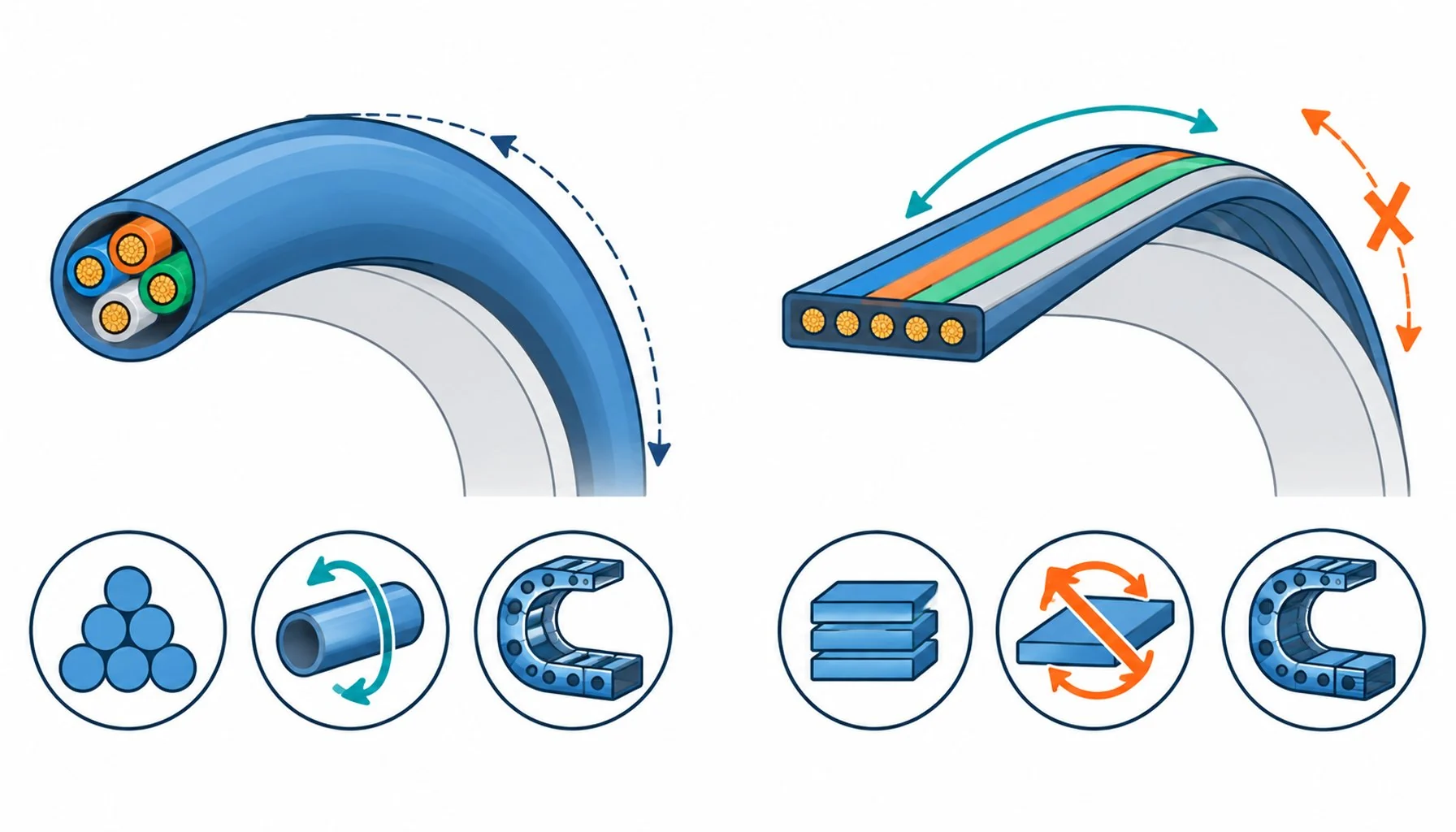
Quick Answer: Flat cable buys routing density and bend control in tight chains; round cable buys robustness, standard hardware and torsion tolerance; the choice is decided by the carrier geometry and the motion, not by preference.
Cable catalogs offer most motion-duty constructions in two shapes, and the shape is not cosmetic. Flat and round cables distribute bending strain differently, fill carrier space differently, tolerate torsion differently and terminate differently. Machines pick the wrong shape often enough that the wrongness has a signature: flat cable installed where torsion lives, round cable forced into a carrier compartment too narrow for it, both failing early while their correctly-chosen siblings run for years. This guide compares the two forms honestly: where each is native, what each trades, how the choice interacts with carrier layout, and the decision table that settles it per axis.
Introduction
The two forms solve the same problem, conducting power and signals through a moving chain, with different geometries. Round cable is the generalist: a long heritage of construction knowledge, standard glands and connectors, and a circular cross-section that tolerates bending in any direction. Flat cable is the specialist: its wide shape lowers the effective bending stiffness in one plane, lays cores side by side for inspection and separation, and packs efficiently in shallow compartments. Neither is better; each is native to a set of conditions, and the conditions are readable from the machine before the first cable is bought.
How the Geometry Changes the Bending
Bend a flat cable against its narrow edge and the outer cores travel farther than in an equivalent round cable, which is why flat constructions are rated to smaller radii in their working plane: the geometry is, in effect, pre-flattened into the shape the bend wants. The condition is the working plane. Bend a flat cable across its wide dimension, twist it, or let it roll in the carrier, and the advantage inverts: the flat construction resists the wrong-plane motion and concentrates strain at the edges. Round cable has no wrong plane, which makes it the native form wherever the motion includes twist, rotation or any path the designer cannot guarantee stays planar.
The practical consequence is a rule of thumb worth memorizing: flat for planar bending duty in managed compartments, round for everything the machine might do unpredictably. Chains that guide the cable faithfully are the flat cable’s home; robot arms and any axis with rotational freedom are round cable’s.
Fill, Separation and the Carrier Layout
Flat cable lays cores side by side, which does two things a round bundle cannot. It makes every core inspectable along the run, a genuine maintenance advantage on complex harnesses. And it packs into shallow carrier compartments with a high fill efficiency, which matters where the chain height is constrained by the machine. Round cable bundles, meanwhile, keep the separation discipline inside the construction, power and signal elements spaced within the jacket, the same logic the control-versus-instrumentation division describes in the guide to control versus instrumentation cable, and they tolerate the dividers and rollers of standard chain hardware without orientation concerns. The carrier layout question is therefore not just flat versus round per cable, but which harness architecture the compartment supports: a mixed harness of flat runs for the planar axes and round constructions for the compound-motion axes is common and completely legitimate, and the separation discipline it inherits is the same one plant-wide power distribution practice applies at every scale.
Weight and volume add a secondary consideration on mobile equipment: flat constructions can shave height and mass from tight platforms, one of the reasons they appear in compact AGV and robot designs where every millimeter of stack height is contested.
Termination and Handling Differences
The forms terminate differently, and the difference is practical rather than cosmetic. Round cable accepts the standard ecosystem of glands, connectors and strain reliefs, the accessories landscape mapped in the guide to cable accessories selection, which matters for replacement speed and hardware availability. Flat cable needs flat-capable terminations or transitions, its strain relief must respect the wide geometry, and its cores, exposed side by side, are convenient to land but need care to keep the bending plane correct right up to the connector. Handling follows the same logic: flat cable has a correct orientation through every bend and every clamp, and installations that respect the marking and the natural curl of the product get the rated life, while installations that twist it into place do not. The termination hardware differences compress into the comparison below.
| Condition | Native form | Why | Mistake to avoid |
|---|---|---|---|
| Planar chain motion, managed compartment | Flat | Bend geometry native, dense packing, core inspectability | Allowing twist or roll into the flat run |
| Torsion, rotation or compound-motion axis | Round | No wrong plane; angular tolerance | Flat cable where the path cannot stay planar |
| Shallow carrier, tight stack height | Flat | Fill efficiency in constrained height | Forcing round bundles into over-narrow compartments |
| Standard hardware, fast replacement | Round | Glands and connectors off the shelf | Flat-specific terminations specified without spares planning |
| Long unsupported spans and gliding runs | Round | Torsional stability over length | Flat runs that roll and edge-load in long spans |
| Compact mobile platform | Either, by layout | Flat saves height; round saves orientation discipline | Choosing form before the chassis geometry is fixed |
Where Each Form Is Native: The Decision Table
The conductor and construction quality behind either form follows the same rules as any motion cable, from the fine-stranding geometry that shares bending strain to the jacket compounds that fight the environment, and the failure patterns that weak construction produces are catalogued in the guide to why cables fail. The form changes the geometry of the bending, not the physics of fatigue.
When the Choice Is Already Made for You
The choice compresses into the table below, read per axis rather than per machine: a single production line can legitimately carry both forms, each where its geometry is native.
| Aspect | Round cable | Flat cable | Practical consequence |
|---|---|---|---|
| Glands and connectors | Standard ecosystem, off the shelf | Flat-capable or transition hardware | Round wins replacement speed; plan flat spares |
| Strain relief | Radial clamping, familiar practice | Must respect the wide geometry and its plane | Wrong flat strain relief concentrates edge stress |
| Core landing | Bundle opened at the end | Cores exposed side by side | Flat lands faster but must keep plane to the connector |
| Orientation discipline | None; tolerates any rotation | Correct plane through every bend and clamp | Installations that twist flat cable forfeit the rating |
| Service inspection | Bundle opened to inspect | Cores visible along the run | Flat offers running inspection on complex harnesses |
RFQ Checklist: Specifying the Form
One caution applies to both columns: form factor never substitutes for construction quality. A flat cable with coarse conductors fails exactly like a round one with coarse conductors, and the verification habits that audit any motion cable apply to both forms equally.
Conclusion
Honest limits: sometimes the geometry decides. Replacement projects inherit the carrier and the terminations, and switching forms mid-life buys disruption, not life; the replacement rule is to match the proven form unless the failure history indicts it. Some machine families are designed around one form, with compartments, rollers and hardware that make the alternative a forced fit. And some duties, extreme torsion, extreme radii, hybrid signal loads, have native constructions in one form and not the other, which the catalog comparison in any serious supplier’s range makes visible. The decision table above is for new designs and open questions; for everything else, the machine’s own history is the better consultant.


