
Hollow Shaft Cable Routing: What to Specify for Through-Arm and Through-Bore Paths
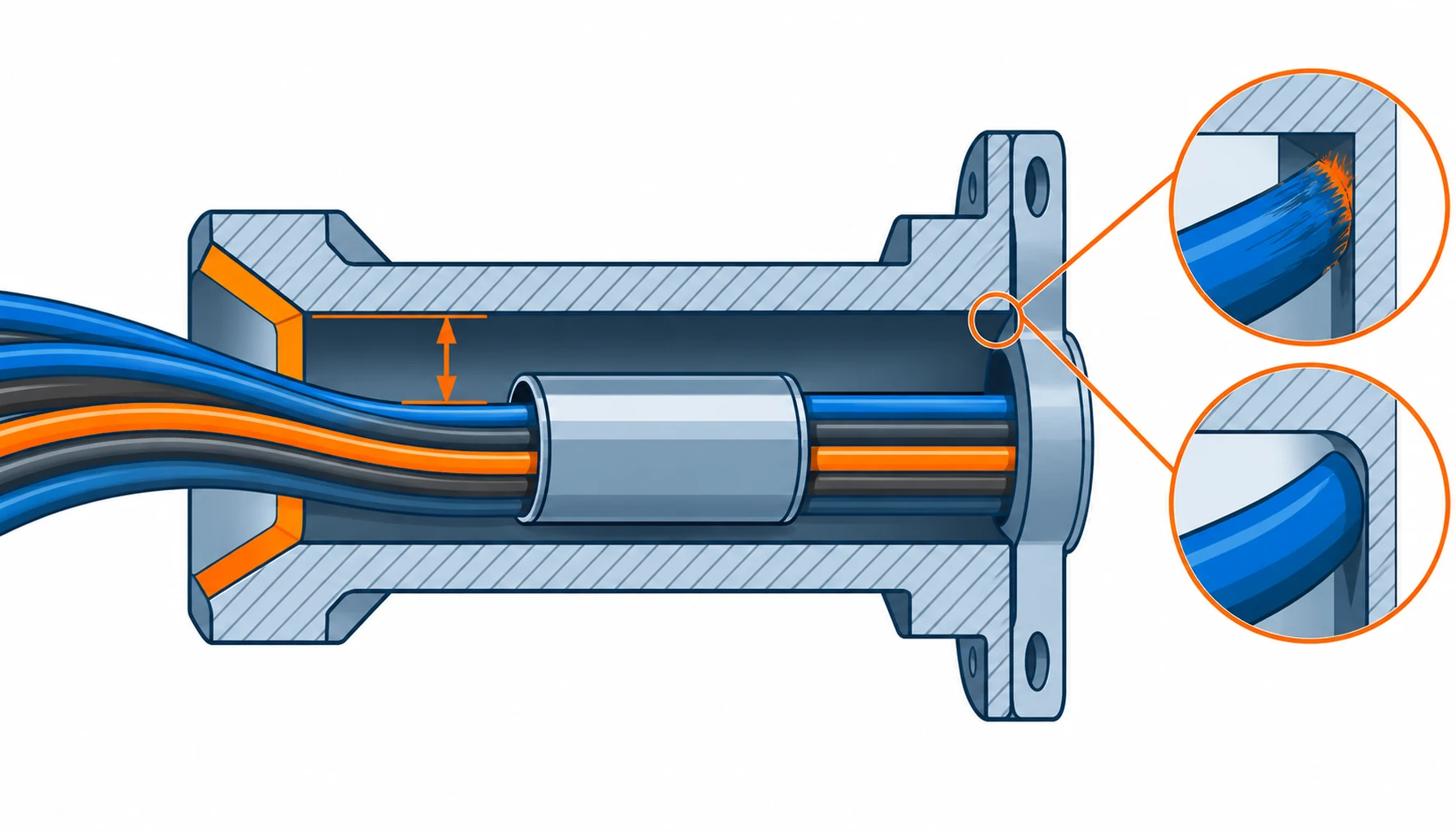
Quick Answer: Running cable through a hollow shaft is the neatest way to get power and signal across an axis. The cable disappears inside the structure, nothing snags on it, and the arm stays clean. The catch is that the bore becomes part of the specification. Clearance, entry geometry, jacket friction, build order and service access all have to be settled before the cable is ordered, because a bundle squeezed through a sharp-edged bore and never measured is a field failure waiting for its first maintenance window.
Introduction
A through-arm route is usually chosen for geometry rather than electrical reasons. The cable has to reach a wrist or tool on the far side of a rotating axis, and the shortest protected path runs through the middle of the joint. That removes a lot of problems at once: no loop to swing, no dress pack to snag, no cable rubbing against the outside of the arm.
It also moves the risk somewhere less visible. Once the bundle is inside the shaft, nobody looks at it again until something fails, and the failure is usually at a place the design never drew. This guide covers what the bore demands: which route to choose, how the entry decides jacket life, what length tolerance is needed, and what to freeze at order time so the route can still be serviced.
Why Route Inside the Axis
Three gains come from routing inside the structure. Protection is the first, because the arm shields the cable from impacts, swarf and washdown. Compactness is the second, since nothing is carried alongside the arm or looped around the joint, which matters on a cobot working next to a person. Interface count is the third, because a route through the centre reaches the far side of an axis without a dress pack, bracket or clips. Where the axis does move, the joint end still needs the service loop logic set out in our note on cable routing through robot joints.
The Constraints of a Bore
A bore imposes four constraints a free route does not. Clearance is the obvious one: the bundle has to fit with room to spare, and the space is fixed by the shaft, not the cable supplier. Edge wear is the second, because every bore has an entry where the cable touches metal as it moves, and a sharp edge abrades a jacket far faster than normal routing. Build order is the third, since the cable is often pulled through before other parts are fitted, which changes when the harness must be delivered. Access is the fourth, and the one buyers forget: if the bundle cannot be disconnected and withdrawn, every service visit becomes a partial rebuild.
The Decision Table: Through-Bore Routes and What Each One Costs
| Route | Cable to Buy | What to Specify | Evidence to Demand | Where It Fails in Service |
|---|---|---|---|---|
| Single bundle through one bore | Small outside diameter continuous flex | Outside diameter against the bore, entry chamfer and clearance gap | A fit sample passed through the actual bore with the real jacket | Jacket abraded at the entry where the cable touches metal |
| Grouped bundles through several bores | Same as above, split by function | Which bundle goes through which bore, and the separation between them | A routing drawing showing each bore and its bundle | Bundles that were swapped at build, putting power next to signal |
| Bundle inside a slip sleeve | Standard flex, protected by a sleeve | Sleeve material, fit over the bundle, and its own clearance in the bore | A sample assembly pushed through the bore by hand | A sleeve that doubles the effective diameter and jams mid-pull |
| Side route beside a split bearing | Continuous flex, tight radius rated | The bend radius around the bearing and the clamp on both sides | A bend test at the radius the side route imposes | Bends tighter than the rating because the bearing gap is small |
| Fixed transition at the shaft end | Continuous flex to a fixed tail | Where the bundle leaves the shaft, and the strain relief at that point | A drawing showing the exit and its relief | The transition point taking all the motion instead of the loop |
Entry Geometry, Slip Sleeves and Clearance
The entry is where a through-bore route succeeds or fails, and it is decided by two features: the chamfer or radius at the mouth of the bore, and whatever sits between the cable and that mouth. A radiused entry lets the bundle bend away gradually, spreading the contact over a longer arc. A sharp or burred entry concentrates the same force on a line of jacket a millimetre wide, which wears through to the screen long before a conductor breaks. Ask for the entry to be drawn, not described, because a chamfer present on a model is often missing on the part.
A slip sleeve is the usual fix where the bore cannot be reworked. It carries the abrasion on a replaceable part instead of the jacket, but it takes up space, so it belongs inside the clearance calculation rather than on top of it. Jacket friction matters too: a low-friction jacket slides instead of gripping, which spreads the wear, and the materials that behave best in a bore are set out in our note on abrasion resistant cable jackets.
Clearance itself is best treated as a percentage of the bore rather than a fixed millimetre figure, because the bundle has to pass through a curved path, not a straight one. A bundle that measures comfortably against a straight gauge can still bind at the midpoint of a curved bore, which is why the fit sample matters more than the arithmetic. The bend the entry imposes is a radius like any other, judged the same way as the values in our note on minimum bend radius.
Serviceability and Length
A route that cannot be serviced gets cut and re-terminated in the field, which is where the cost of a through-bore design reappears. Decide at order time whether the harness can be disconnected at both ends and pulled out of the bore without dismantling the axis.
Length follows from the same answer. A bundle pulled through needs enough length to be handled at each end, plus the tolerance for the curved path inside the bore. Too short, and it sits in tension along the whole route, loading connectors and entry together. Too long, and the surplus has to go somewhere, which in a bore means it folds or bulges against the wall. The service and swap logic is set out in our note on robot cabling serviceability, where the access path decides the design.
Where a route cannot be made serviceable, the honest option is to treat the harness as a consumable with a defined replacement procedure, written into the order as a replacement interval and a spare part rather than discovered by a maintenance team.
What to Freeze Before the Order
| Item | What to State | Evidence to Attach | Cost of Leaving It Open |
|---|---|---|---|
| Outside diameter | The bundle diameter against the bore, with the clearance gap stated | The actual bore diameter and a fit sample | A bundle that fits on paper and binds inside the curved bore |
| Entry treatment | The chamfer or radius at every bore mouth the cable passes | A drawing of the entry, checked on the first part | Jacket wear on a sharp edge, opening the screen in service |
| Slip sleeve | Whether a sleeve is used, its material and its fit over the bundle | A sample assembly drawn through the bore by hand | A sleeve that jams mid-pull, or one that was never included in the clearance |
| Jacket friction | Jacket material and its behaviour against the bore surface | A drag test in the actual bore or a matched sample | Grip instead of slide, concentrating wear at one point |
| Length and tolerance | The length needed for the curved path, plus handling length at each end | A first-article measurement after assembly | Tension along the route, loading connectors and the entry together |
| Build order | When the harness must be delivered to be fitted before other parts | A build sequence note in the order | A harness delivered too late to be routed, forcing a field splice |
| Service access | Whether the harness can be disconnected and withdrawn from the bore | A removal procedure, or a stated replacement interval | Every service visit ending in a partial rebuild |
| Routing drawing | One drawing per axis, showing the bore, the entry and the clamps | The drawing revision tied to the part number | A route that lives only in the head of whoever built the first unit |
When a Through-Bore Route Is Not the Answer
Where the bore is too small for the bundle. Squeezing a bundle through an undersized bore to keep an existing casting is false economy. The clearance is gone, entry wear is worse, and the build slows on every unit. Change the casting, split the bundle, or route outside the arm.
Where the bundle has to be serviced often. A bore route that cannot be opened in place turns a fifteen-minute cable swap into a shift. Where the harness has a short service interval, or the machine runs a duty where cable replacement is expected, an external route is the better answer even though it looks less tidy.
Where the joint also rotates continuously. A through-bore route does not solve continuous rotation, because the bundle still winds up. Where an axis turns without a hard stop, the cable has to be replaced by a rotating transfer, and that decision belongs at the start of the design rather than after the route is frozen.
Where the cable was chosen for the outside of the arm. A construction chosen for a dress pack is not automatically right for a bore, because a bore rewards small diameter, low friction and a tough jacket rather than a thick, armoured build. Where one harness serves both an internal route and an external run, the two sections may need different constructions, and the split is the subject of our note on internal wiring versus a dress pack.
RFQ Checklist
- Bundle outside diameter stated against the actual bore, with a clearance gap for the curved path
- Entry chamfer or radius drawn for every bore mouth the cable passes, and checked on the first part
- Slip sleeve named if used, with its material and its fit over the bundle included in the clearance
- Jacket material chosen for friction against the bore, not only for flexibility
- Length and tolerance stated for the curved path, plus handling length at each end
- Build order written into the order, so the harness arrives before the parts that close the route
- Service access settled at order time, with a removal procedure or a stated replacement interval
- Disconnect points identified at both ends, so the harness can be withdrawn without dismantling the axis
- One routing drawing per axis, showing the bore, the entry and the clamp positions
- Abrasion evidence requested for the jacket against the bore surface, not only a general wear claim
Conclusion
A through-bore route can remove an entire class of field problem, and it can also hide a new one where nobody looks. The bore is part of the cable specification: its size sets the outside diameter, its entry treatment sets the jacket life, its build order sets the delivery, and its access decides whether the harness is a part or a consumable. Settle those four at order time and the route stays tidy for the life of the machine.
Kexingyu Cable Group (KXYE) supplies the cable side of through-shaft and through-arm routes: small diameter continuous flex constructions, including the robot composite cable, built with the jacket toughness and low friction such a route needs, and with the stranding to take the bend the entry imposes. Send us the bore drawing, the axis motion and the service plan, and we will return constructions and sample lengths that fit; the fastest route is a request for quotation.


