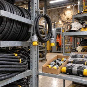
TBM Cable: Specifying Supply, Reeling and Communication Cable for Tunnel Drives
Quick Answer: A tunnel boring machine buys three cable systems: the high voltage feed that follows the machine up the tunnel, the reeling and trailing cables on the machine’s own drums, and the communication composite cable that carries data to the face. The tunnel decides the specification: everything is wet, confined, and expensive to reach once the drive starts. Fix the voltage level and the drum geometry first, demand test evidence per drum, and buy the communication line as a composite rather than as an afterthought.
Introduction
Tunnelling is the least forgiving cable environment in construction. The tunnel never dries, access is one-dimensional, and a cable fault partway through a drive stops a machine whose standing cost is measured in tens of thousands per day. Once the segments are built and the machine has advanced, replacing a run means working in a finished tunnel with limited windows.
That changes the procurement logic. Cable for a tunnel drive is bought for the whole drive, with spares, testing and delivery sequence planned as part of the package, and the specification conversation happens before the machine assembles, not after the first fault.
What Tunnel Duty Does to Cable
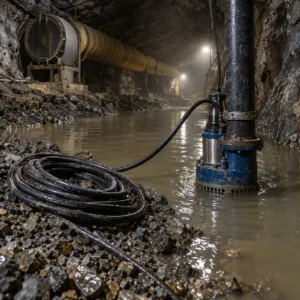
Water everywhere. Invert water, groundwater, flushing and slurry systems keep every cable wet for the life of the drive. Water blocking and splash-resistant construction are baseline, not options.
Confinement and handling. Cable is handled in tight spaces, around gantries and through restricted clearances, and every metre pulled is pulled by hand or winch in poor conditions.
Moving machine. The TBM advances continuously; supply and communication cables re-reeve on machine drums and gantry systems thousands of times per drive.
One chance to install. Fixed runs along the lining are installed once, in a sequence tied to ring build. A run that arrives late or in the wrong lengths becomes a surface jointing exercise with a machine waiting, and the standing cost of that machine makes it the most expensive slip in the schedule.
The High Voltage Supply Line
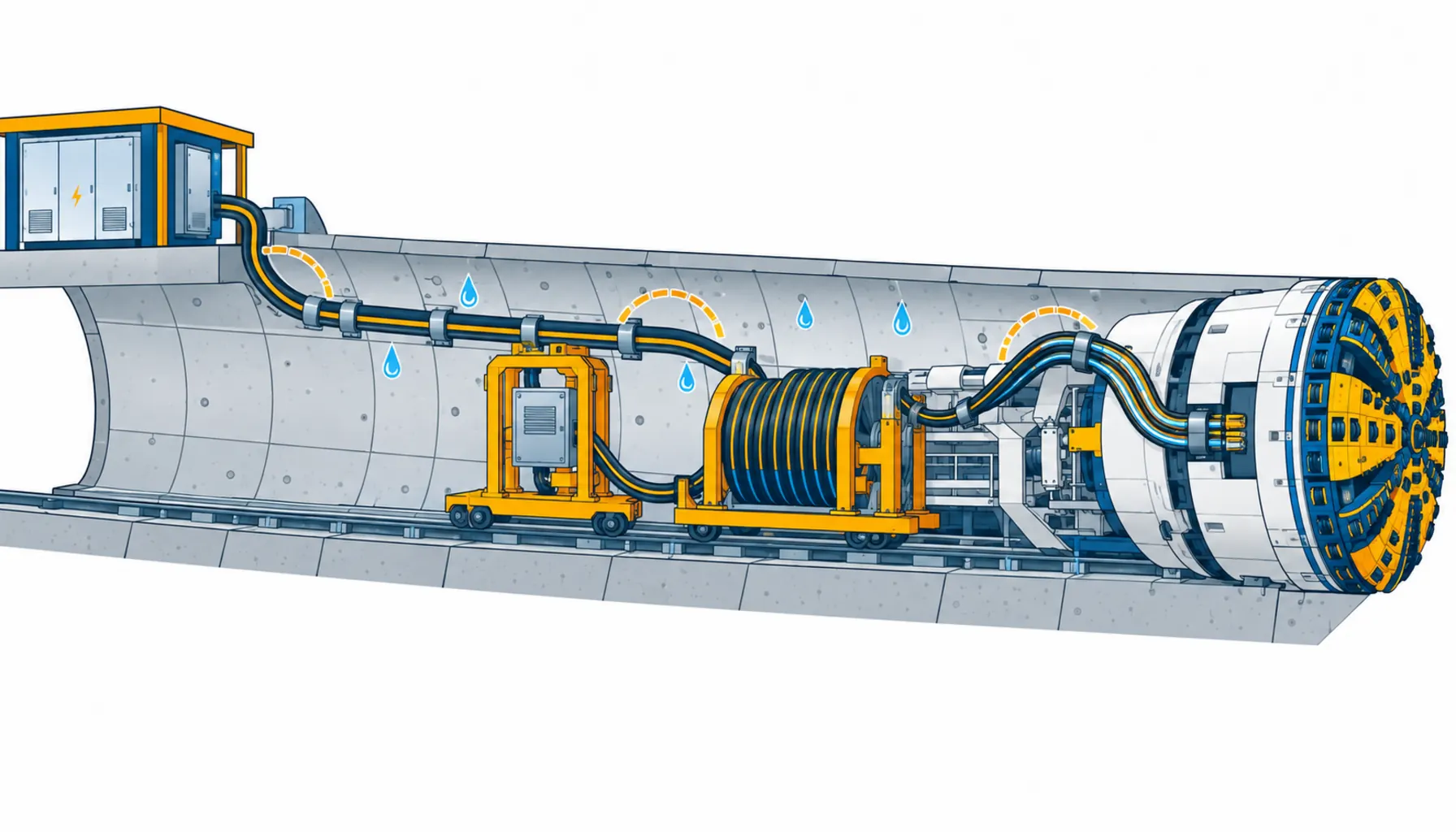
The main feed to a TBM is usually medium or high voltage, brought from the portal substation along the tunnel, stepping down at gantry transformers close to the machine. The distance grows every week the drive runs, which shapes the whole procurement line.
Voltage level and armoured construction. State the system voltage, the insulation level and the fault level at the gantry. Armoured construction is standard for the tunnel run, selected with the earth fault protection scheme in mind. Armoured medium voltage constructions of the type used on tunnel feeds are covered in our note on medium voltage armoured cable.
Length strategy. Tunnel feeds are ordered in drum lengths matched to the pulling and jointing sequence, with joint positions planned as the drive grows. State drum sizes and the tunnel’s handling limits: a drum that cannot travel the tunnel is a problem discovered on site.
Power close to the face. The step-down architecture decides how much cable the order really needs, and it is why prefabricated substations on skids have become the normal answer on long drives: the feed stays at a economical voltage for as long as possible, and the heavy current runs only where it must.
Machine Reeling and Trailing Cable
The machine itself winds and unwinds cable on drums as it advances: power to the gantries, control between stations, and services to the back-up. The duty is reeling under tension in a wet tunnel, and the specification reads like mobile plant cable with the environment turned up.
Drum geometry first. Entry radius, winding pattern and working tension decide the construction, exactly as on cranes and rigs. Where the winding twists the cable, a torsion-rated construction is the baseline; our note on torsion cable construction covers the difference, and reeling-rated options are covered in our note on reeling cable for drums and machines.
Water and abrasion. The cable lies in invert water between advances. Water-blocked construction and a heavy sheath are the baseline; the minimum bend radius at every drum and guide must be confirmed against the real geometry, and our note on cable minimum bend radius explains where datasheet optimism shows up.
| System | Duty | What to Specify | Evidence to Demand | Cost and Lead-Time Driver | How It Fails |
|---|---|---|---|---|---|
| High voltage tunnel feed | Fixed along the lining, wet, length grows with the drive | Voltage and insulation level, armoured construction, water blocking, drum lengths to the jointing sequence | Factory test reports per drum, partial discharge data, sheath and armour construction drawing | Copper content and jointing kit schedule dominate; certification sits in the lead time | Water ingress at joints, armour corrosion, damage at pulling points |
| Machine reeling and trailing cable | Reeved under tension on machine drums, wet, confined | Reeling duty and torsion rating, drum geometry, water-blocked construction, heavy sheath, screen continuity | Reeling cycle test at declared tension, torsion test where winding twists, continuity per length | Reeling-rated construction premium; continuous lengths set the clock | Sheath cuts, water ingress, conductor fatigue at drum entries |
| Communication and data composite | Reels with the machine, carries network to the face | Composite construction with power and optical or data elements, bend performance of the data element, screen separation | Attenuation or insertion loss data flexed at drum radius, composite construction drawing | Composite designs are made to order; the data element sets the quality bar | Power circuits running fine while the data element degrades, ending remote operation |
| Services and lighting runs | Fixed along the tunnel, handled during extension | Splash-resistant construction, extension module lengths, connector standardisation | Ingress protection ratings, continuity records | Stock constructions; standardisation saves more than unit price | Connector failures in standing water, damaged sections during ring build |
Communication: The Line That Ends Drives
TBMs are operated, monitored and coordinated through a data link to the face, and the cable that carries it is reeled, flexed and wet like everything else on the machine. The failure pattern is the uncomfortable one: power circuits keep running while the data element degrades quietly, and the first symptom is lost telemetry or a dropped remote link at a critical moment.
That is why composite cable, built with the power cores and the optical or data elements in one sheathed construction, has become the default on modern machines: one drum, one handling routine, and the data element engineered for the same bend cycle life as the power cores. Composite constructions of the type used on machine drums are covered in our note on the network composite reel cable. Demand attenuation data for the data element measured after flexing at the drum radius, not on a straight sample.
Thermal and Derating in a Tunnel
Tunnel heat is trapped heat, and it changes the sizing conversation. Machines, transformers and long runs of loaded cable share one volume of air with limited ventilation, and ambient at cable height is not the figure at the portal.
State the real ambient. Ask the drive’s ventilation design what temperature the cable environment reaches at the working face and along the gantries, and size against that number. A feed sized at standard ambient in a warm tunnel loses margin exactly where the load is heaviest.
Grouping. Power, communication and services run side by side along the same lining. Grouped circuits derate, and the high voltage feed sitting against services runs is the case that gets forgotten. Ask for the derated current for the actual grouping, with the calculation shown.
Drum thermal limits. Cable coiled on a machine drum between advances carries full current in its worst thermal position. Confirm the drum duty with the supplier rather than assuming the open-run figure, and note it in the machine’s operating instructions so the crew knows what the drum can hold continuously.
None of this raises cost much when it is specified up front; it is one conductor step, decided once. Discovered after the drive starts, the same margin costs a re-order into a tunnel that is already built, which is the expensive version of the same decision.
What to Freeze Before the Drive Starts
| Decision | What to State | Evidence to Attach | Cost of Leaving It Open |
|---|---|---|---|
| Voltage architecture | Feed voltage, step-down points, fault level at the gantry | Single line diagram for the drive | An uneconomical feed and a re-engineered supply |
| Drum lengths and jointing | Drum sizes to the pulling sequence, planned joint positions | A jointing schedule mapped to ring build | Joints in the wrong places for the whole drive |
| Drum geometry on the machine | Entry radius, winding pattern, tension per drum | Machine manufacturer's data or measurements | Reeling cable that under-performs on the actual drums |
| Composite data design | Data element type, bend performance, screen separation | Attenuation after flexing at drum radius | A machine that loses its link mid-drive |
| Water defence | Water blocking, splash ratings, gland scheme | Construction declarations per system | Invert water in the insulation within a season |
| Test and witnessing plan | Factory tests, site tests, witnessing points per drum | Written plan with acceptance criteria | Volume accepted on paperwork nobody verified |
| Delivery sequence and spares | Drums phased to the drive schedule, spare lengths held | Delivery plan against ring build | A machine standing in a finished tunnel |
Lead Time and Cost Structure
TBM cable lines are long-lead by nature. High voltage feed with factory testing and jointing kits runs six to ten weeks and phases with the drive start; reeling and composite constructions run four to eight weeks against drum geometry. Order the full drive schedule with the first order, not drum by drum, because manufacturing slots for long continuous lengths book out.
On cost, the high voltage feed carries the copper weight of the order, and the machine lines carry the engineering premium. Two commercial clauses matter more here than almost anywhere: a copper basis with a validity window, because drive programmes quote far ahead of order, and a delivery sequence contractually tied to ring build, because a drum that arrives late is not late by a week but by the drive’s critical path.
Incoming Inspection
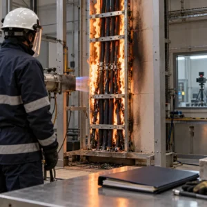
Factory and site testing. High voltage feed is factory-tested per drum, and the drive should witness or require records of the routine tests, plus partial discharge where the voltage class calls for it. On arrival, verify drum condition and markings against the packing list, and re-test continuity, insulation and screens on the machine lines before they are fitted.
Independent verification. On drives where a client’s engineer sits over the works, third-party verification of the test evidence is increasingly standard; our note on third party cable inspection covers how to run it without slowing the delivery.
When a TBM Cable Specification Is Not the Answer
When the drum guide is eating cable. Reeling cable failing at one machine drum needs the guide and geometry checked first. The tunnel makes replacements slow, which is exactly why the geometry review is worth the stop.
When the data fault is a termination. Degrading telemetry that responds to re-termination rather than replacement is a connector or gland problem. Swap the spare composite section, confirm, then fix the termination properly.
When the feed architecture has moved on. If the drive has extended well past the design assumptions, the voltage drop and joint count arguments change. Re-derive the architecture rather than ordering another drum of the same feed.
When services are being patched per ring. Repeated repairs on lighting and services runs are an extension-and-connector standardisation problem, and the fix is procedural, not a heavier cable.
RFQ Checklist
- Feed voltage, insulation level and fault level, with the step-down architecture
- Drum lengths mapped to the pulling and jointing sequence
- Machine drum geometry: entry radius, winding pattern and tension per drum
- Reeling cycle and torsion test evidence at the declared geometry
- Composite data design with attenuation after flexing at drum radius
- Water blocking and splash ratings per system, with the gland scheme
- Factory test reports and witnessing points per drum
- Delivery sequence against ring build, with spares and their storage
- Copper basis with validity window, and revision rules for the drive schedule
Conclusion
TBM cable is bought as a drive-length package: voltage architecture and jointing frozen before the machine assembles, reeling and composite lines engineered to the machine’s real drums, and every drum tested against a written plan. Buy it drum by drum and the drive buys the failures instead.
Kexingyu Cable Group (KXYE) has manufactured cable in Quanzhou since 1996, including armoured medium voltage feed, reeling and composite drum constructions used on tunnel drives, with factory testing and drive-schedule delivery plans. Send us the drive’s single line diagram and drum geometry, and we will come back with constructions per system, the test evidence and a phased delivery plan. The fastest route is a request for quotation.