
Crimping, Soldering or IDC: Terminating Robot Harnesses Reliably
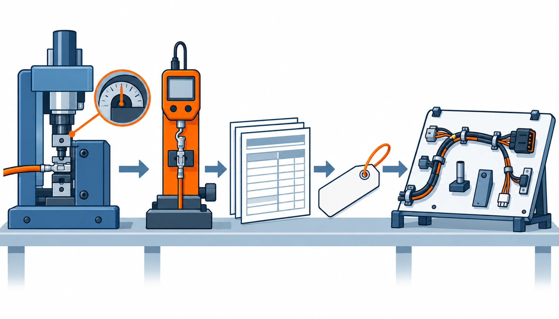
Quick Answer: A harness termination is the only part of the electrical system made by hand or by tool on the day your order ships, and it is where intermittent faults live. Crimping is the default for anything that moves: a gas-tight joint, made by calibrated tooling, evidenced by pull-off force records from the shipped batch. Solder belongs only where the joint is static and strain-relieved, because solder turns a stranded conductor into a stiff wire that fractures at the transition. IDC belongs in cabinets on stable multi-pair runs. None of this is visible in the finished harness, which is exactly why the specification and the batch records matter more than inspection.
Introduction
The cable construction gets specified in the datasheet; the termination gets decided at the bench. That asymmetry is why harness faults so often trace back to joints that were never anyone’s written responsibility: a crimp made with worn tooling, a solder joint that wicked into the strands, an IDC block pressed by hand instead of by press. The harness overview in our note on robot harnesses and connectors sets out the assembly element by element; this guide goes into the termination itself, method by method, with the process controls that keep each one honest.
The stakes are simple. A broken conductor is a clean failure that continuity testing finds in minutes. A poor termination is an intermittent one: it passes the bench, ships, and appears on the third shift as a fault nobody can reproduce, which is the most expensive failure class in automation.
Crimping: The Default for Moving Machinery
A proper crimp is not a squeeze; it is a controlled cold-weld. The contact has two barrel zones, one forming around the conductor strands, one around the insulation, and the tool closes them to a height specified by the contact maker to hundredths of a millimetre. Done right, the strands cold-weld into a gas-tight mass that survives vibration better than any other joint and stays flexible immediately behind the barrel, which is why crimping is the only sensible default on moving axes.
The discipline lives in the process, and the specification should demand it item by item: tooling calibrated to the contact maker’s crimp-height window, a pull-off force requirement per contact size, and records traceable to the shipped batch rather than to a qualification run from a year ago. Workmanship acceptance criteria are written down in the industry harness standard IPC/WHMA-A-620, and naming it in the RFQ gives both sides a shared definition of “acceptable”. Our note on connector contact plating covers the other half of the joint, the plating the crimp compresses.
The Decision Table: Termination Methods and Where Each Belongs
| Method | Where It Belongs | What to Specify | Evidence to Demand | Where It Fails in Service |
|---|---|---|---|---|
| Crimp | Default on moving axes, drag chains and any flexed route; connector contacts of every family | Contact maker's crimp-height window, tooling calibration regime, pull-off force per contact size | Batch pull-off force records and crimp height readings traceable to the shipped lot | Under-crimped joints that pass continuity and drift in resistance under vibration |
| Solder | Static, strain-relieved joints in cabinets and on PCBs; never on flexed routes | Joint class per IPC standard, strain relief behind every joint, a no-solder clause for moving axes | Workmanship photographs or first-article inspection against the stated class | Wicking into the strands making a stiff wire that fractures just behind the joint |
| IDC / mass termination | Cabinet wiring on multi-pair and ribbon runs; stable, low-flex routes only | Approved cable construction for the block, press tooling not hand pressing, pair assignment drawing | Press records and gas-tight verification per the block maker's process | Cold gas-tight bonds on the wrong cable construction, opening up under vibration |
| Screw terminals | Static cabinet walls, power distribution, serviceable connections | Wire end ferrules, torque value and torque marking, re-torque schedule where vibration exists | Torque specification and ferrule standard named on the assembly drawing | Backed-out screws under vibration, stranded conductors pinched without ferrules |
| Ultrasonic splicing | Joining conductor runs inside molded harnesses where a connector contact is not used | Splice cross-section requirement, pull strength per splice, insulation overmould specification | Splice pull-test records from the batch | Brittle or cold splices from wrong energy settings, found only after molding hides them |
Soldering: Where It Belongs and Where It Creates Risk
Solder’s bad reputation in harness work is earned, and it is worth understanding why. Molten solder wicks along the strands between the conductors of a stranded wire, and where it stops, the flexible stranded conductor becomes a solid rod. Every flex cycle the harness takes is now concentrated at that transition, and the conductor eventually fatigues there: not at the joint, which looks perfect, but a few millimetres behind it. On a moving axis this is a scheduled failure; the solder joint itself will outlive the machine.
That is a reason for rules, not for prohibition. Solder is the right answer where the joint is genuinely static and supported: on PCBs, at cabinet terminals with strain relief, and inside assemblies where nothing moves. The specification should say exactly that: solder permitted on static routes with strain relief behind every joint, prohibited on moving axes and flexed routes, joint class named against the relevant IPC workmanship standard. Where a supplier proposes solder on a flexed route to save crimp tooling, the saving is real and so is the failure; our note on servo cable construction shows what the flexed route does to everything behind the joint.
IDC and Mass Termination: Fast, and Narrowly Qualified
Insulation displacement contacts slice into the insulation and bond to the conductor in one press, which makes them fast and repeatable for the right cable: solid or fine-stranded constructions designed for the block, on routes that do not flex. The failure mode is silent: an IDC bond that is not gas-tight still reads continuity at the bench and oxidises its way to an open circuit over months of vibration. The defence is narrow qualification: only the cable constructions the block maker approves, pressed by the press the block maker specifies, never by hand pliers, with the pair assignment controlled by drawing. In cabinets and backplanes that discipline pays; on a robot arm it does not belong.
Process Control: Tooling, Records and the Operator Question
Every method above converts into reliability only through process control, and the controls are cheap to specify and expensive to retrofit. Calibrated crimp tooling with a maintenance record. Crimp height monitoring on the press, with action limits. Pull-off force testing per batch, against the contact maker’s minimum values, with the readings tied to serial numbers. Operator qualification for manual operations, refreshed when tooling changes. And for the assembly as a whole, the qualification route in our note on robot cable sample testing brings the harness and its terminations under one acceptance plan before volume.
The operator question deserves its own line in supplier audits: ask who terminates, how they were qualified, and what happens when a crimp height reading drifts. A supplier with answers has a process; a supplier without them has a bench.
What to Freeze Before the Order Goes Out
| Item | What to State | Evidence to Attach | Cost of Leaving It Open |
|---|---|---|---|
| Method per route | Crimp on moving axes, solder only static and strain-relieved, IDC only in cabinets | A termination schedule mapped to the harness routing | Method chosen at the bench, and fatigue failures scheduled into the harness |
| Crimp window | Contact maker's crimp-height window named per contact | Tooling calibration and crimp height records | Under- and over-crimps that both pass continuity and both fail later |
| Pull-off requirement | Minimum pull-off force per contact size, tested per batch | Batch pull-off records traceable to shipped serial numbers | No way to prove joint quality after a field fault appears |
| Workmanship standard | IPC/WHMA-A-620 class named for the harness | First-article inspection against the stated class | "Acceptable" defined differently by each side of the order |
| Ferrule discipline | Ferrules on every stranded conductor at screw terminals | Ferrule standard on the assembly drawing | Pinched strands and backed-out screws in cabinet distribution |
| Strain relief behind joints | Relief geometry behind every solder joint and connector backshell | Detail drawings or approved samples | Conductor fatigue just behind perfect-looking joints |
| Operator qualification | Named process for qualifying and refreshing operators | Qualification records reviewed at audit | Quality that depends on who was on shift |
| Repair policy | Field repair method permitted per failure class, and what must go back to the factory | A written repair procedure with tooling list | Field fixes that introduce the very faults the specification excluded |
When a Termination Specification Is Not the Answer
Where the failure is really the routing. A conductor broken just behind a connector can be a gland mismatch or a bend radius problem wearing the harness, and no crimp improvement will fix it; our note on why robot connectors fail separates the signatures. The entry geometry itself is covered in our note on the strain relief and connector interface.
Where every joint is being gold-plated. Static cabinet wiring does not need aerospace crimp discipline, and paying for batch pull-off records on terminal blocks that never move is spend the project does not recover. Match the controls to the duty: strict on flexed routes, proportionate everywhere else.
Where the sealed environment was forgotten. A perfect crimp in a connector that parks open in a washdown zone still fails; the sealing conditions are judged separately in our note on IP ratings for robot connectors.
Where the boundary families were crossed. Termination requirements travel with the connector family: what applies inside an M23 power insert differs from a cabinet terminal block, and the family-level logic is in our notes on M8 and M12 connectors and on heavy-duty rectangular connectors.
RFQ Checklist
- Termination method named per route class: crimp on moving axes, solder only static and strain-relieved, IDC only in cabinets
- Contact maker’s crimp-height window named per contact, with tooling calibration regime
- Pull-off force minimum per contact size, tested per batch, records traceable to shipped serial numbers
- IPC/WHMA-A-620 class named as the workmanship acceptance standard
- Ferrules required at screw terminals, with the standard named on the assembly drawing
- Strain relief geometry specified behind every solder joint and connector backshell
- IDC restricted to block-maker-approved cable constructions and press tooling
- Operator qualification and crimp monitoring regime described by the supplier at audit
- Sample qualification protocol covering the finished harness, not just the cable
- Written field repair policy defining what may be repaired on site and what returns to the factory
Conclusion
Termination is where a harness specification meets a human process, and the reliable designs are the ones that respect both: crimp for everything that moves, solder where nothing does, IDC where the block maker’s process can be enforced, and batch evidence behind all of it. None of these requirements costs much at order time. All of them move failures from the third shift back to the test bench, which is the only place they are cheap.
Kexingyu Cable Group (KXYE) supplies the cable side of terminated assemblies: the continuous flex and torsion constructions whose stranding, jacket and screen geometry are designed to take a proper crimp and hold it for the life of the machine. Send us the routing and the connector schedule, and we will return the constructions and sample lengths that fit; the fastest route is a request for quotation.


