
Gripper and Tool Changer Cable: Buying for Quick-Change Interfaces
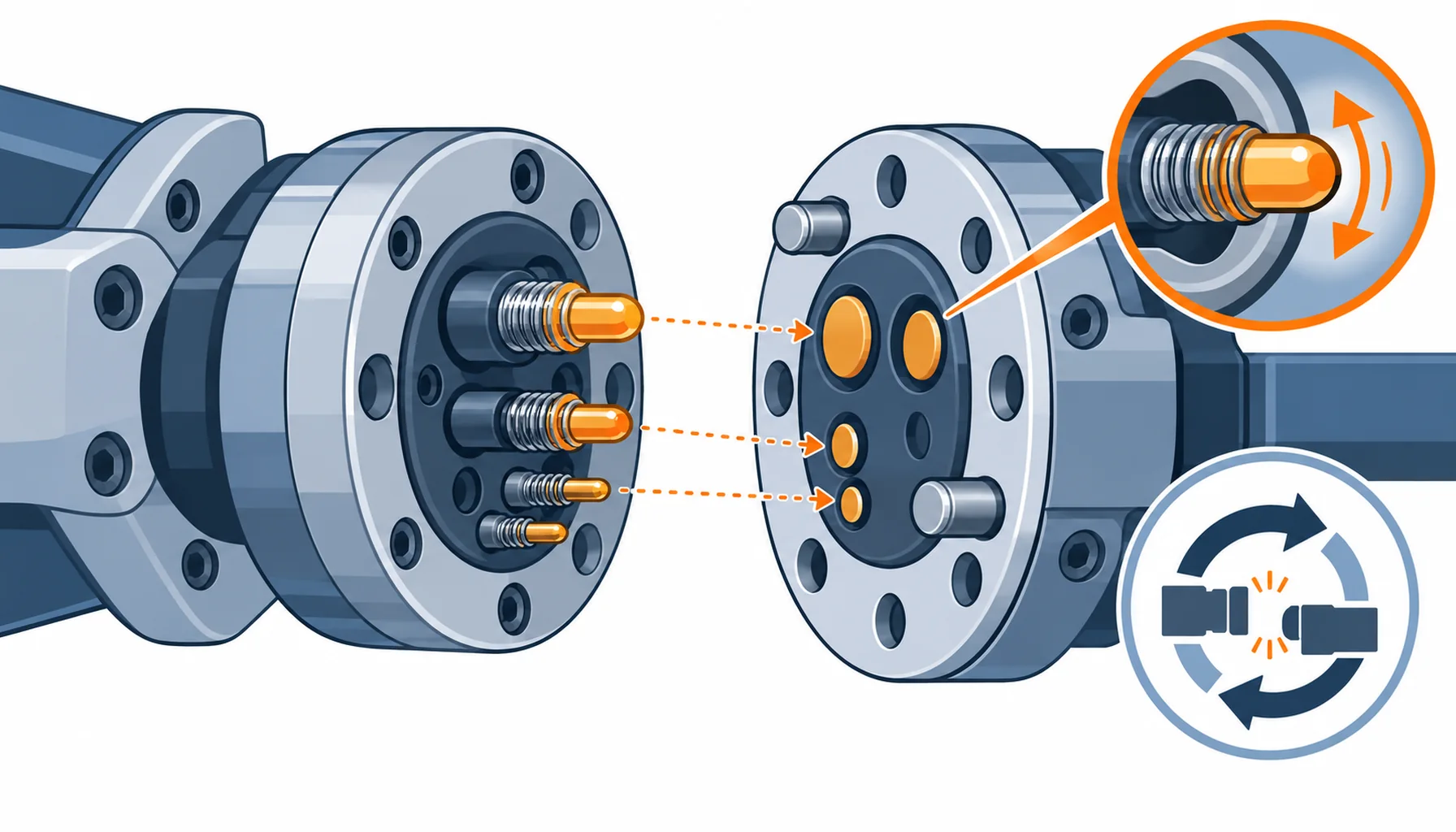
Quick Answer: A quick-change interface decides how power, signal and air get to the tool, and every one of those paths wears a little each time the tool is swapped. The five common approaches, hard wired, contacts in the module, spring pins, contactless coupling and a cable reel, differ in what they cost, what they tolerate and how they fail. Buy on the mate cycle count you actually expect, not the one in the brochure, and settle whether the tool needs air and signal as well as power before the interface is chosen.
Introduction
A tool changer looks like a mechanical part, but it is an electrical and pneumatic interface as well, and it is the part of the cell that changes hands most often. Each swap has to break and remake every power, signal and air connection, and each of those cycles uses up a little of the life of whatever carries them.
The cable zone this sits in is covered in our note on end effector cable. This guide stays on the interface itself: how power and signal cross a quick change, what each method costs over the life of the cell, and what to write into the order so the changer is not the reason a tool swap is avoided.
What a Quick Change Does to the Cable
Three duties meet at a changer. The first is carry, because power, signal and often air have to cross the joint with the tool fitted. The second is repeat, because the joint is designed to be broken and remade, and every opening and closing is a wear cycle on the contacts, the seals and the alignment features. The third is tolerate, because a changer has to work when the two halves are slightly misaligned, slightly dirty, or carrying a load that flexes the arm.
The cable’s job is the part that usually gets least attention. A tail that runs from the arm to the moving half of the changer bends every time the tool changes and again on every cycle that moves the tool, so the tail sees a combined duty that is heavier than the tool’s own motion and heavier than the arm’s.
The Five Ways to Carry Power and Signal to a Tool
The choice is not only electrical. A hard-wired tool is the cheapest and the most reliable until someone has to change tools a few hundred times a day, and then the labour is the cost. Contacts built into the changer move the wear into a designed, replaceable part, which is usually the right answer at volume. Spring pins suit small signals and low currents but lose contact force over time. Contactless coupling removes contact wear entirely at the cost of efficiency and alignment tolerance. A reel or drag chain carries power to a moving tool without a changer at all, and is often the right answer where the tool only has to reach, not to swap.
Power and signal paths behave differently at the interface. A power pair can tolerate modest contact resistance, because the voltage is high and the current is steady. A signal or a sensor line cannot, because a small rise in resistance or a little electrical noise shows up as a fault. That is why a changer carrying a gripper sensor or a bus connection needs a specification for the signal path on its own, not one number for the whole interface.
The Decision Table: Five Interface Approaches and What Each One Costs
| Interface | Cable to Buy | What to Specify | Evidence to Demand | Where It Fails in Service |
|---|---|---|---|---|
| Fixed tool, hard wired | Continuous flex with a service loop | Loop length, bend radius and the points the tail is clamped | A flex test at the radius the loop imposes | The loop pulled straight at the end of travel |
| Contacts built into the changer | Short flex tail to the module | Mate cycle count, contact rating and the replacement interval | A mating cycle test to the stated count | Contact wear and intermittent faults after many swaps |
| Spring pin contacts | Flex tail, low force contacts | Contact force, wipe and the minimum signal level carried | A cycle test with contact resistance measured throughout | Force loss and rising resistance on small signals |
| Contactless coupling | Fixed cables on both sides | Alignment tolerance, power level and separation distance | A coupling test at the worst alignment | Efficiency loss and heat at the limit of the gap |
| Cable reel or drag chain | Reel or chain rated cable | Reel cycle count, bend radius at the take-off and the loop shape | A reel test at the specified cycles and radius | Jacket wear where the cable leaves the reel |
Contact Wear and Mate Cycle Count
Every contact in a changer is a wear part, and the only question is how many cycles it gets and how it is replaced. A changer that is opened twice a shift is a different purchase from one that is opened two hundred times, and the same interface can be entirely adequate for one and hopeless for the other.
The number that matters is the mate cycle count over the life of the cell, not the count per day. Multiply the swaps per shift by the shifts and the years you expect, and ask for a mating cycle test at that figure. Contact plating, contact force and wiping action decide how the wear progresses, and these are the same mechanisms that end a connector’s life anywhere else on the machine, set out in our notes on connector contact plating and on why robot connectors fail. A changer whose contacts fail early usually shows up first as an intermittent fault on a sensor rather than as a clean break, which is why the signal path deserves its own number.
Air and Signal at the Interface
Air is the line that buyers most often forget to specify. A gripper that needs a vacuum or a blow-off needs a passage through the changer, and that passage is a bore with its own sealing, its own alignment tolerance and its own wear. A passage that leaks slightly will still hold a light part and fail on a heavier one, so the leak rate and the pressure duty belong in the order as numbers rather than as a general claim about sealing.
Signal lines have a mirror-image problem. A screened or bus line through a changer has to keep its shielding across the interface, and each half needs the other to keep the screen continuous, in the same way a screened cable needs a shell to bond to. The environmental side of the same interface, including the sealing of the whole module, is covered in our note on IP ratings for robot connectors.
What to Freeze Before the Order
| Item | What to State | Evidence to Attach | Cost of Leaving It Open |
|---|---|---|---|
| Functions to carry | Power, signal, sensor line and air, listed separately | A pin or passage schedule for the interface | A changer that cannot carry a function added later |
| Mate cycle count | Swaps per shift multiplied by shifts and years of service | A mating cycle test to that count | Contacts worn out inside the warranty period |
| Power and signal rating | Current per power contact and the signal level carried, stated apart | Contact resistance measured through the cycle test | Intermittent sensor faults that look like a control problem |
| Contact material | Plating and contact force chosen for the mate count, not the price | A plating specification and cycle evidence | Early wear on the one contact that carries the weakest signal |
| Air passage | Bore size, working pressure and the maximum leak rate | A leak and flow test at the working pressure | A gripper that drops parts it should hold |
| Screen continuity | How the screen stays continuous across the two halves | A bond or continuity check across the mated interface | Noise on a bus line through the changer |
| Alignment tolerance | How far the halves may be misaligned and still mate correctly | A first-article check at the worst case | Contacts that mate only when the arm is positioned perfectly |
| Replacement interval | Which parts are wear parts, and the interval for each | A parts list with the swap procedure | A changer treated as permanent that is really a consumable |
When a Tool Changer Is Not the Answer
Where the tool is hardly ever swapped. A changer adds contacts, seals and alignment features that all wear, and a cell that changes tools a few times a year does not earn that back. A hard-wired tool with a good service loop is simpler and has fewer failure modes.
Where the signals are delicate. Fine sensor or bus signals through a mechanical interface are a known problem area, and if the only reason for the changer is a function that could be carried by a separate flexible tail, that tail is often the better answer. Do not route your weakest signal through your most-worn interface if a route around it exists.
Where the tool only has to reach. If the tool moves but is not exchanged, a reel or a drag chain carries power without any contact wear at all, which is why they dominate on machines that stroke rather than swap. The choice between a changer and a moving feed is a motion question first and an electrical question second.
Where the interface has never been maintained. A changer is a wear part, and if the maintenance plan treats it as permanent it will fail in service. Where a site has no habit of inspecting contacts and seals, the simplest interface, or a moving feed with no contacts to inspect, is often the more reliable purchase. Downtime costs on this scale are set out in our note on robot downtime cost.
RFQ Checklist
- Functions listed separately: power, signal, sensor line and air, each with its own rating
- Mate cycle count stated over the life of the cell, with a cycle test to that count
- Current per power contact and signal level per signal contact specified apart
- Contact plating and force chosen for the mate count, with cycle evidence
- Air bore, working pressure and maximum leak rate stated as numbers
- Screen continuity across the mated interface shown on a drawing or checked on a sample
- Alignment tolerance specified with a first-article check at the worst case
- Wear parts identified, with a replacement interval and a parts list
- Flex tail to the changer rated for the bend it takes at every swap and every cycle
- A swap procedure written down, with the time it takes and the tools needed
Conclusion
A tool changer is bought as a mechanical part and paid for as an electrical and pneumatic one, because the wear that stops it is on contacts, seals and signal paths rather than on the locking mechanism. Decide what has to cross the interface, work out how many times it will be opened, and specify the wear parts so they can be replaced on a plan instead of after a fault.
Kexingyu Cable Group (KXYE) supplies the cable side of quick-change interfaces: short continuous flex tails and reel rated constructions, including the robot composite cable, built to take the bend at every swap from the arm to the tool. Send us the interface schedule, the swap count and the tail route, and we will return constructions and sample lengths that fit; the fastest route is a request for quotation.


