Tunnel Cable for Lighting and Ventilation: Selection and What to Freeze
Quick Answer: Tunnel cable is mostly short-circuit current and volt drop over distances that a building never sees, feeding motor loads that are now driven by variable speed drives and lighting that is switched in stages as a driver moves through the tunnel. Add a fire mode in which the ventilation has to keep running, and the requirements become quite specific: padded conductor sizes for volt drop rather than for current, drive-rated screened construction for the fan feeds, and circuit integrity where the smoke extraction strategy depends on it.
Introduction
A tunnel is a confined duct with services inside it, a control room at one end and a fire strategy that assumes the ventilation has to run when everything else stops. Lighting is arranged in adaptation sections that switch as vehicles pass, and fans are now almost always speed-controlled so the ventilation can be matched to air quality rather than run flat out.
Both changes push the cable specification away from a normal building package. This guide covers the load behaviour, the two calculations that decide the conductor size, and the decisions to freeze before the order.
Why Tunnel Circuits Behave Differently
Distance dominates the calculation. A tunnel lighting or fan circuit can run over a kilometre from the nearest switchboard. On those lengths, volt drop rather than current-carrying capacity usually sets the conductor size, and the difference between a compliant and a non-compliant design is often two standard sizes.
Fans are variable speed driven. Speed control brings harmonic current, a high frequency leakage current to earth through the motor cable capacitance, and reflected voltage pulses on long motor leads. A standard power cable on a long drive-to-motor run is the most common source of insulation failure and nuisance earth leakage tripping in a tunnel.
Lighting is switched in stages, continuously. Adaptation lighting means banks of luminaires switching on and off all day as traffic changes, so the circuits see many more operations than a building circuit and the switching device and cable see repeated inrush.
Fire mode reverses the design intent. In a fire the ventilation may be required to run in smoke extraction mode, and the lighting may be required to stay on in the escape route. Those circuits are bought on circuit integrity at a stated grade, which is a different purchase from the ordinary duty circuits beside them.
The environment is damp and uncleaned. Tunnels leak, wash-down systems operate, and the atmosphere is often laden with brake and tyre dust. Insulation and sheath selection has to assume permanent moisture rather than occasional wetting.
Tunnel Cable Scopes
| Scope | Duty | What to Specify | Evidence to Demand | Cost and Lead-Time Driver | How It Fails |
|---|---|---|---|---|---|
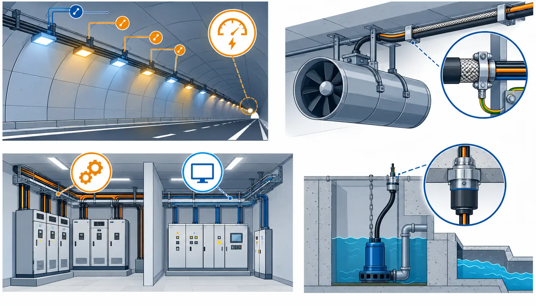
| Adaptation and escape lighting | Staged switching all day, long runs, moisture, and survival in fire mode on escape sections | Conductor sized on volt drop at the furthest luminaire, construction suitable for permanent moisture, circuit integrity grade on escape sections | Volt drop calculation, insulation and sheath test data, survival test evidence for the escape circuits | Copper padding for volt drop; the survival sections are a small metreage at a high unit rate | Dim lamps at the far end of the tunnel from a circuit that passes its current check |
| Jet fan and booster fan feeds | Drive fed motors, long motor leads, high starting current, permanent damp | Screened drive cable with the screen termination convention stated, conductor on the drive output duty, separate protective conductor sized for leakage current | Drive manufacturer requirement, screen termination detail, earth leakage calculation, type test data for the cable | The screening and the drive requirement rather than the copper; fan positions decide the run | Nuisance earth fault trips, or insulation punctured by reflected pulses after a few years |
| Ventilation plant and control rooms | Dense motor and control cabling, harmonic rich, accessible for maintenance | Derating for grouped and enclosed containment, segregation between drive and control circuits, motor control centre arrangement | Derating calculation, segregation drawing, protection and co-ordination study | Boards and drive panels rather than cable; the control room drives the lead time | Derating ignored on a tray that was sized for cable count rather than thermal capacity |
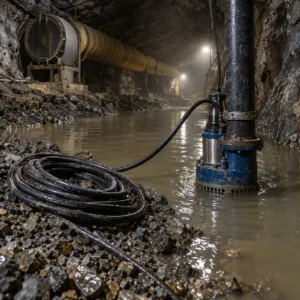
| Pumping, drainage and sumps | Submerged or frequently wet, accessed rarely, motor starting in a wet environment | Water resistant or submersible construction, sealed terminations, protection against mechanical damage at the sump | Water and insulation resistance test data, ingress rating at the termination, installation record | Sealing and terminations, because access to repair a sump cable is expensive | Water tracking into a termination and a pump that trips only during heavy rain |
| Monitoring, control and communications | Long signal runs in the same corridor as drive cables, safety critical for incident detection | Screened or fibre where the distance and interference demand it, segregation from power containment, spare capacity for later systems | Screen continuity or fibre test records, segregation drawing, spare capacity stated | Signal cable and the containment rather than the copper; upgrades follow incidents | Incident detection failing intermittently because the signal run shares a route with a drive cable |
The Two Calculations That Decide the Conductor
Tunnel circuits are sized by two numbers, and on long runs they disagree with what a capacity table suggests.
Volt drop at the furthest point. Calculate against the last luminaire or the furthest fan, not the first, and include the drive where one is fitted. Where lighting is distributed along the tunnel, a ring or a distributed arrangement can reduce the conductor size more cheaply than a heavier radial, and the decision belongs at design stage because it changes the circuit count. Our note on voltage drop calculation sets out the calculation order.
Derating in a confined and grouped installation. Tunnel services run in trays and ducts that are shared, enclosed and often warm, and the derating factor on a long grouped tray is significant. Our note on cable derating factors covers the factors that apply; the failure mode is a tray sized by cable count and a circuit that runs hot in service.
The drive output needs its own treatment. A variable speed drive output is not a sinusoidal supply. Long motor cables increase the capacitance to earth, which raises leakage current and creates reflected voltage pulses at the motor terminals. The practical answers are to keep the motor cable run short where possible, to use screened cable with the screen terminated at both ends in the prescribed way, and to fit a dv/dt filter or output reactor where the distance cannot be reduced. Our notes on variable speed drives versus soft starters and on the arrangements around the motor control centre cover where those decisions are normally made.
Moisture, Terminations and the Long Term
Assume permanent damp. A tunnel is a wet environment even when it is not flooded. Cable with a construction suited to immersion or heavy wetting, sealed glanding and terminations that prevent water tracking along the conductor are the three requirements, and all three are more important than the conductor size. Our waterproof cable range covers the constructions used in wet service, and a rubber sheathed option such as H07RN-F splash resistant rubber cable suits the mobile and semi-permanent plant in a tunnel plant room.
Bend radius at every direction change. Tunnel routes follow the lining, cross the crown and drop into cabinets, and the tightest bend is usually at the termination rather than in the run. Specify the minimum radius and check it at the cabinet, because a cable forced into a cabinet entry is a cable with a shortened life. Our note on cable minimum bend radius gives the figures and the common exceptions.
Earthing and bonding in a structure that is also an electrode. Tunnel linings, reinforcement and running rails all interact with the earthing system. Verification of the bonding arrangement is part of the cable package because the cable terminations form part of it. Our note on grounding and bonding verification covers what to record at handover.
Penetrations at the portals and cross passages. Every cable that leaves the tunnel passes a boundary that has to maintain the fire compartment, and the penetration is a system rather than a sealant. Our note on firestop cable penetrations covers what the approved detail has to include and why partial approvals are the usual failure.
What to Freeze Before the Order
| Decision | What to State | Evidence to Attach | Cost of Leaving It Open |
|---|---|---|---|
| Volt drop limit | The percentage limit and the point it is measured at, per circuit group | A volt drop calculation to the furthest luminaire or fan | A circuit that meets its current rating and dims or stalls at the far end of the tunnel |
| Drive fed motor cable | Screen type and termination convention, and any filter or reactor needed by the run length | The drive manufacturer's cable requirement plus the termination detail | Earth leakage trips, or insulation failure a few years into service |
| Protective conductor sizing | Protective conductor sized for the drive leakage current, not just the fault current | Earth leakage calculation for the run length | A protective conductor that carries continuous leakage current and degrades |
| Moisture and ingress | Construction for wet service, gland and termination type, sump protection detail | Water and insulation test data, ingress rating at the termination | Water tracking into a termination that is difficult to reach and expensive to remake |
| Fire mode circuits | Which lighting, ventilation and control circuits must run in fire mode, at what grade | Survival test evidence plus approval covering fixings and terminations | A smoke extraction strategy that cannot be demonstrated at commissioning |
| Segregation inside the tunnel | Separation between drive cables, power circuits and signal routes | A segregation drawing matched to the containment layout | Incident detection and control faults that appear only when the fans are running |
| Termination and cabinet access | Bend radius, cabinet entry arrangement and the space allowed for glanding | Detail drawings with the radius shown at each entry | Cable damage at the cabinet that is found years later and blamed on the cable |
When a Tunnel-Grade Cable Specification Is Not the Answer
When volt drop is being solved with copper instead of with the circuit arrangement. A distributed or ring arrangement often costs less than two extra conductor sizes on a radial, and it also reduces the fault level at the far end.
When the drive nuisance tripping is being solved with a heavier cable. Leakage current and reflected pulses are solved by screening, screening termination and filtering. A larger conductor does not reduce any of them.
When a long motor cable is being accepted because the plant room is convenient. Moving the drive closer to the fan, or moving the fan position, is often cheaper than every cable and filter measure needed to make a long run work.
When entrance and escape lighting are specified at the same grade as the ordinary lighting. Only the circuits the fire strategy depends on need survival performance, and paying the grade premium across the whole tunnel lighting installation is a large avoidable cost.
RFQ Checklist
- Volt drop limit and the furthest point for each circuit group
- Derating factors for the tray, duct and ambient condition along the route
- Which circuits must run in fire mode, with survival grade and the standard behind it
- Drive manufacturer requirement for motor cable, screens and any output filter
- Protective conductor sizing including the drive leakage current allowance
- Construction for wet service, plus gland and termination type per location
- Sump and drainage circuit construction with sealed terminations
- Segregation distances between drive, power and signal containment
- Bend radius and cabinet entry detail at every termination point
- Penetration systems at portals and cross passages, listed as complete assemblies
- Earthing and bonding records required at handover
Conclusion
Tunnel cable is decided by distance and by fire mode rather than by current. Size the circuits on volt drop to the furthest point and derating in a grouped tray, treat the drive fed fan cables as a different product from the ordinary power cables beside them, assume permanent moisture at every termination, and buy circuit integrity only on the circuits the smoke extraction and escape strategy actually names. Those four decisions cover most of what goes wrong in a tunnel installation.
Kexingyu Cable Group (KXYE) has manufactured cable in Quanzhou since 1996, supplying screened drive cable, fire-rated constructions, water resistant sheaths and control cable for infrastructure work, with the test records a commissioning engineer will ask for. Send us the circuit schedule, the drive requirements and the fire mode list, and we will come back with the constructions, the sizing basis and the accessories that suit the route. A request for quotation is the fastest route.