Hydropower Cable for Kyrgyzstan and Tajikistan: Dams, Penstocks and Switchyards
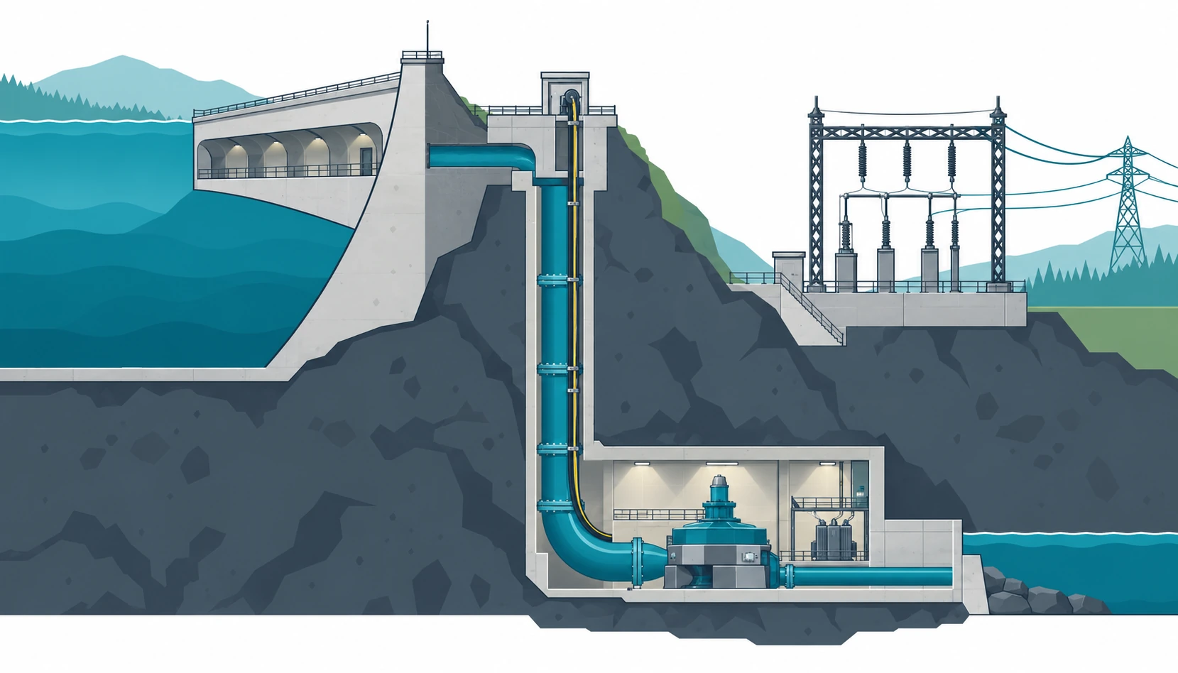
Quick Answer: A hydropower scheme buys cable for three wet places, and each one fails for a different reason. Galleries inside the dam stay damp for the life of the plant and are inspected once a year at best; penstock shafts are vertical, so the cable carries its own weight and water runs down the outside of it; the switchyard is outdoors, cold in winter and full of single-core runs. Sort every circuit into one of those three zones, then fix the water protection, the support and the derating for that zone. A single “wet location” note on the datasheet covers none of them.
Introduction
Kyrgyzstan and Tajikistan both build on rivers that fall fast, and both run ageing plants that are being rehabilitated unit by unit. The cable work in either case looks small next to the turbines and the gates, which is exactly why it is bought late, in a hurry, and against a schedule written for a thermal power station.
This guide is for EPC buyers, plant electrical engineers and distributors supplying cable into hydropower projects in the two countries. It covers the three duty zones, what water does to each of them, vertical support in shafts, derating inside a machine hall, and the fields to freeze before the order. Medium voltage selection for the auxiliary feeders is set out separately in our note on medium voltage cable standards.
Three Duty Zones and What Each One Breaks
The tender usually arrives as one cable schedule for the whole scheme. That is the first thing to break. A gallery lighting circuit, a shaft pump feeder and a switchyard connection share a voltage and very little else, and the sheath that suits one is wrong for the next two.
Galleries inside the dam. Permanently damp, lit by a few lamps, with cable trays bolted to concrete that sweats. The failure here is not dramatic: insulation resistance drifts down over years and is found during an annual test, on a circuit that has been wet since it was pulled.
Penstock shafts and vertical drops. The cable hangs. Its own weight pulls on the top clamp, and any water in the shaft runs down the outside of the sheath into the first gland it reaches. Both problems are mechanical, and neither is solved by a better compound.
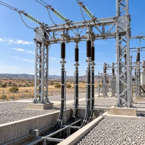
Switchyard and outdoor terminations. UV, ice, wind, and single-core runs between equipment that is replaced on a different schedule from the cable. Terminations here are re-made by whoever is on shift, so the arrangement has to be simple enough to survive that.
Water in Three Forms
Condensation is the one nobody writes into the specification. A concrete gallery holds a steady low temperature through the summer. Warm humid air comes in through the access shaft, meets the coolest surface available, and the cable sheath is often that surface. The mechanism and the countermeasures are described in our note on condensation on wet sites.
Seepage is slow and continuous. Water moves through the dam body into the gallery drains and keeps the floor wet and the air close to saturation. Nothing is immersed, and everything is damp, which is the harder case to specify because there is no single number to design against.
Immersion is local and predictable. Drainage sumps, gate slots and the low sections of a gallery during inspection are genuinely underwater at times. A pump feeder that ends in a sump is immersed by design, and the construction for that duty is on our submersible pump cable page.
Three mechanisms, three products. Water blocking and a bedding that resists standing damp answer condensation and seepage; a fully sealed construction answers immersion; a sheath choice answers the splash in between. The family that covers the middle ground is on our waterproof cable page.
Hydropower Cable by Duty Zone
The table groups the circuits that appear in most hydropower enquiries, with the decision each one forces.
| Duty Zone | What to Declare | Evidence to Ask For | Cost and Lead Time | Risk If Left Open |
|---|---|---|---|---|
| Dam gallery and drainage | Humidity, standing water, inspection interval, fire load in the gallery | Water blocking data plus sheath and bedding details | Standard sections, short slots | Low insulation resistance found years after commissioning |
| Penstock shaft and vertical run | Total drop, support spacing, water running on the cable | Armour type, safe working load, clamp design | Longer drums, more joints, longer slot | Armour stretched at the top clamp, cores drawn tight |
| Powerhouse machine hall | Ambient at tray height, circuits per tray, oil mist | Derating calculation with ambient and grouping stated | Standard, oversized once derating is counted | Section short in the hottest bay |
| Switchyard and outdoor termination | Single or three-core, screen bonding, ice and UV exposure | Screen and sheath data with a bonding diagram | Single-core costs more per metre | Circulating current in armour, hot joints |
| Auxiliary and control circuits | Segregation, fire survival for emergency circuits, EMC near excitation | Fire test report and screen details | Moderate, longer on fire-rated lines | Emergency lighting lost in the same event as the fault |
Vertical Runs, Support and Joints
A cable in a penstock shaft is a mechanical problem first. Steel wire armour will carry its own weight up to a point, and the point is set by the clamp spacing and by the load the armour can take without the strands bedding into each other. Ask for the figure rather than assuming the standard drum works. The comparison of armour types is in our note on steel wire armour selection.
Joints in a shaft are an access decision. A joint needs a platform, a permit and a unit shutdown, so the drum length is chosen to put joints in the gallery or at the shaft head instead. That planning step is the one covered in our note on drum length and jointing strategy, and it is cheaper to do at enquiry stage than on site.
Water follows the cable down. A run that enters a shaft from above should be looped before the entry so that water sheds at the bottom of the loop instead of running into the gland. The loop costs a metre of cable and saves a termination.
Single-core in a shaft needs non-magnetic support. Steel clamps around a single core form a closed magnetic path, and the resulting heating appears at the clamp, not at the joint. Specify the clamp material with the cable, not after.
Derating Where the Plant Runs Warm
A machine hall is hot, and the trays are hotter. The design ambient in the brief is usually taken at floor level; the trays sit near the roof, above the generators, where the air has already passed the machines. Ask for the ambient at tray height and derate against that figure rather than the one in the covering letter.
Grouping decides the section more often than ambient does. Unit auxiliaries, cooling water pumps, governor hydraulics and the crane all leave the same wall in dense trays. The method for combining the two effects is in our note on cable derating factors.
Oil mist and dust are part of the thermal case. A tray coated in a decade of mist sheds heat differently from a clean one, and cleaning inside a powerhouse is a scheduled activity with a permit attached. If the schedule does not exist, the specification should say so.
Excitation, Governor and the Circuits Nobody Lists
The unit auxiliary schedule stops at the motor, and the interesting cable starts after it. Excitation, governor control, vibration monitoring and the unit protection scheme are all small circuits, and they run through the same galleries as the power feeders with a fraction of the attention.
Excitation equipment is a noise source. A thyristor bridge switching a large current will find any unscreened pair that runs beside it, and the symptom is a temperature reading that nobody trusts rather than an obvious fault. Screened pairs, earthed at one end per the design, and a route that keeps some distance from the bridge, are cheaper than the investigation that follows.
Governor hydraulics bring oil and heat together. The cable near a hydraulic cabinet sees oil mist and a warm enclosure, and the two together age a PVC sheath faster than either alone. The control family that suits this duty is on our control cable page.
Drums, Access Roads and Storage
On a mountain site the drum is a transport problem before it is a cable. A long drum that will not pass a switchback on the access road is a joint on the gallery floor, and the joint was never in the programme. Ask what the site can receive, then set the drum length from that answer.
Storage decides more sheath than the datasheet does. Drums standing in the open for a season collect water in the lagging and UV on the outer wraps, and a cable installed after that has been wet since it arrived. Covered storage, drums on their sides, and a delivery phased to the pull are all procurement decisions.
Crossing a border adds documentation to the lead time. Country of origin, test certificates and packing lists travel with the drums, and a certificate that names a different construction than the one on the drum stops the delivery at the frontier. Our note on drum packaging for export covers what the paperwork has to match.
Hydropower Cable Order Freeze List
These are the fields to settle before the purchase order is placed.
| Item to Freeze | How to Write It Into the Order | Evidence to Attach | Cost of Leaving It Blank |
|---|---|---|---|
| Duty zone per circuit | Gallery, shaft, hall or yard marked against every line | Schedule with the zone column completed | One sheath bought for three environments |
| Water protection | Water blocking, bedding and sheath type named | Test data for the construction offered | Water in the core within two wet seasons |
| Vertical support | Total drop, clamp spacing and armour load stated | Support and clamp calculation | Armour strand break at the top clamp |
| Drum length and joint position | Joint locations named, drum length matched to each shaft | Drum schedule per shaft and gallery | A joint platform that was never built |
| Ambient and grouping | Hall ambient at tray height, circuits per tray | Derating calculation | Section short in the hottest bay |
| Fire-rated circuits | Circuits named, with duration and test category | Report naming the construction and the duration | Emergency circuits lost with the fault |
| Switchyard bonding | Screen and armour bonding arrangement, single-core spacing | Bonding diagram with the termination details | Circulating current and hot terminations |
When a Standard Wet-Location Cable Is Not the Answer
When the run is immersed rather than damp. A feeder ending in a sump sits underwater whenever the sump fills, and a splash-rated sheath is the wrong product however good its test result. Reroute the gland above the high level, or buy the submersible construction.
When the shaft is longer than one drum. A joint halfway down a penstock shaft is a joint nobody will inspect, and holding two cable ends in a vertical duct during a shutdown is not a job to discover on site. Split the run at the shaft head instead.
When the gallery is also the escape route. Cable in a single means of escape carries a fire load, and the specification has to reflect that with sheath choice and with fire-stopping at the penetrations. It is a fire decision that lands on the cable buyer.
When the plant is a rehabilitation. Existing trays, existing glands and existing clamp spacing decide more about the new cable than the datasheet does, because nothing upstream is being replaced. Survey the route before the enquiry, not after the order.
RFQ Checklist
- Circuit schedule with the duty zone marked on every line
- Humidity and standing water described for each gallery run
- Total drop and clamp spacing given for every vertical run
- Armour type and safe working load stated for shaft cables
- Joint positions decided, and drum lengths matched to them
- Ambient at tray height and circuits per tray given for the hall
- Water blocking or immersion construction named where it applies
- Fire-rated circuits listed with duration and test category
- Single-core runs listed with bonding arrangement and clamp material
- Termination and gland scope agreed between cable and switchgear suppliers
- Drum lengths matched to the lifting capacity inside the gallery
Conclusion
Hydropower cable is bought in small quantities against a large programme, which is why it gets the least attention and causes the longest outages. The three zones are not difficult to separate once somebody does it on paper: gallery, shaft, yard. What follows from each of them is a short list of decisions about water, weight and heat, and none of those decisions gets easier after the drums arrive.
Kexingyu Cable Group (KXYE) supplies water-blocked, armoured and submersible constructions, medium voltage auxiliary feeders and fire-rated control cable from Quanzhou, and quotes hydropower enquiries against the duty zone as written, with test documents per drum. Send the single line diagram with the zone column filled in, or upload the cable schedule. A request for quotation is the fastest way to start, the enquiry format is set out in our industrial cable RFQ checklist, and the sourcing picture for the region is in the Kyrgyzstan supplier guide.