
How AI Data Centers Change Cable Design vs Traditional Facilities
Quick Answer: AI facilities squeeze more compute, and therefore more current, into every square metre — so cable design shifts to higher rack densities, parallel low voltage feeders, liquid-cooling-aware routing, hotter allowable environments and stricter fire performance, while the cable families themselves stay the same.
Introduction
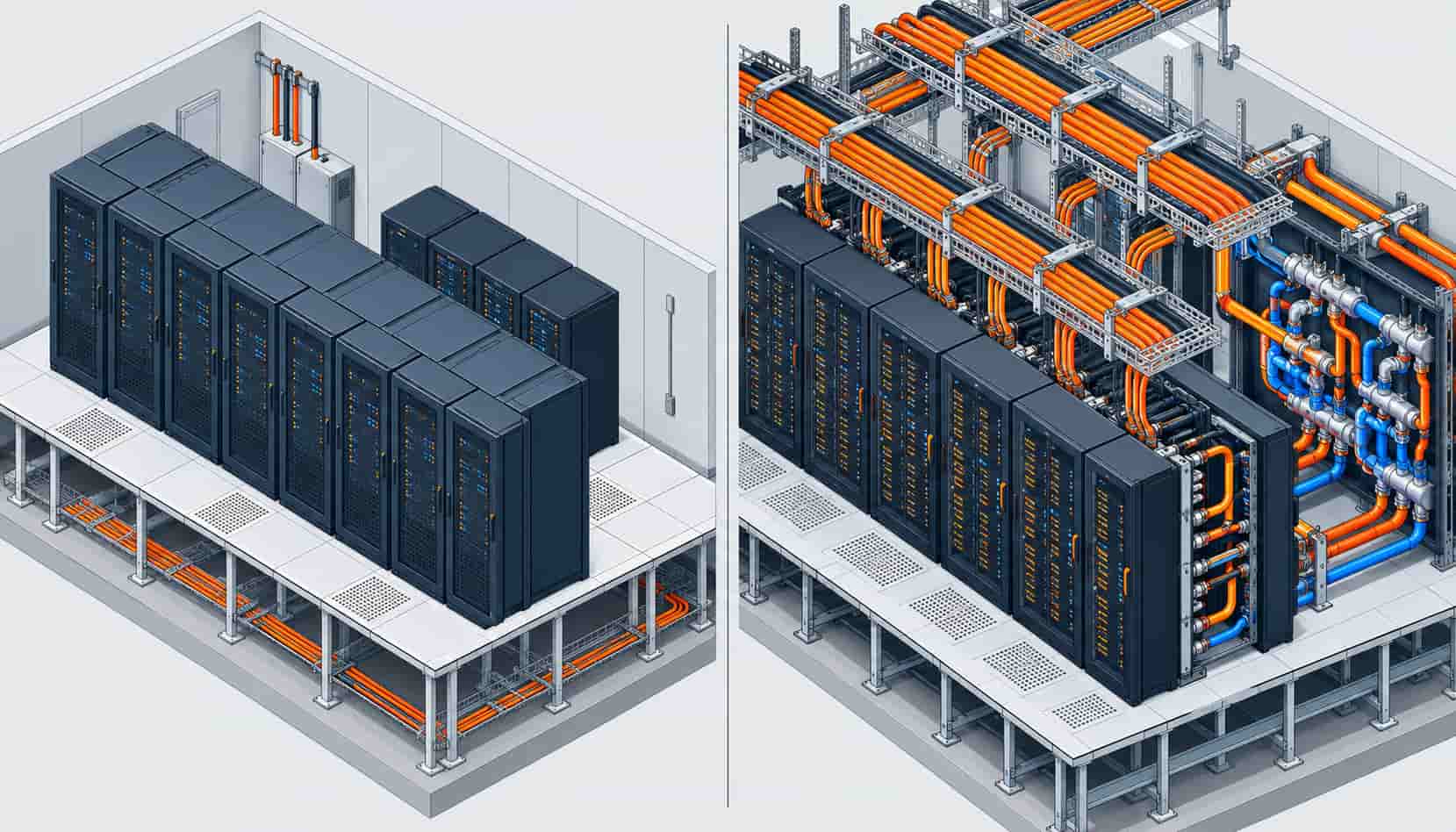
Training clusters did not just make data centers busier; they changed the electrical shape of the building. A hall designed around 6-8 kW racks and air cooling distributes power one way. The same floor plate filled with 30 kW GPU racks, rear-door heat exchangers and liquid cooling manifolds distributes power in an entirely different way — and the cable system is where that difference becomes physical.
This article compares cable design in traditional and AI-era facilities family by family, so buyers and consultants can see exactly which specification lines need to move. The market context matters too: analyst houses project data center cable demand to keep climbing through the decade as AI capacity concentrates in a handful of regions, a trend we follow in data center power demand growth. And when the design conversation widens from cable to the full electrical room, our data center power collection covers the switchgear, UPS and transformer side of the same chain.
Density Is the Design Variable: From 8 kW Racks to 30 kW and Beyond
Traditional enterprise halls treated cable as a routing problem: enough feeders to each rack row, ampacity sized with comfortable margins, and space was rarely the constraint. AI clusters invert that. When a single rack draws 30 kW or more, the current per rack row multiplies several times over, and every metre of cable route becomes contested space. Three consequences follow: feeders are run as parallel single-core sets because no single multi-core carries the current, conductor cross-sections move up to the 300-400 mm2 class, and ampacity calculations must assume loaded trays rather than the sparse groupings of older designs.
The physics does not change — XLPE insulation at 90 °C, derating for grouping and ambient — but the margins do. A design that passed comfortably at 8 kW per rack can be thermally marginal at 30 kW with the same cable in the same tray. Our explainer on what XLPE cable is covers the insulation logic, and UPS sizing for data centers shows how the load side of the calculation scales.
Liquid Cooling Rewrites the Routing Plan
Air-cooled halls put power cable in raised-floor plenums and overhead ladders in predictable corridors. Liquid-cooled AI halls fill the under-floor volume with coolant distribution piping, manifolds and drop hoses, and the racks themselves sit closer together. Cable routing moves decisively overhead, into basket trays and busway-adjacent corridors that must now carry far more current than before — in the same physical space as services that used to be the only occupant.
Routing changes also alter the cable itself. Tighter tray fills and more bends raise the value of flexible, fine-stranded conductors; shorter but hotter routes push designers toward higher-temperature sheath compounds; and the presence of coolant infrastructure makes low smoke zero halogen jackets a baseline rather than an upgrade, because any electrical fault in a shared route should not corrode the cooling plant it sits beside.
Voltage: Higher Low Voltage, and a New DC Layer
Traditional facilities worldwide settled on 400/230 V or equivalent LV distribution, and most of that remains. AI halls push the same voltage harder — 415/240 V systems feeding denser PDUs — and add an emerging layer of DC distribution at 240 V and 336 V for hyperscale and colocation designs, which reduces conversion stages between the rectifier and the rack. The cable implication is subtle but real: DC runs change how ampacity and protection are calculated, and the trend toward higher bus voltages keeps everything on standard 0.6/1 kV products while demanding tighter quality control on insulation consistency.
Redundancy Gets Physical: A/B Feeds in the Same Aisle
Concurrent maintainability was always a paper requirement; AI availability economics make it a cabling requirement. A/B feeds now terminate inside the same aisle, which means two independent feeder sets share the route geometry, and mutual heating between the A and B sets enters the derating calculation. Designers who treat the two feeds as thermally independent overestimate available ampacity; designers who model them correctly size each set for its true grouped rating. The topology logic is the same one behind N+1 versus 2N UPS redundancy — redundancy that shares a failure domain is not redundancy.
| Cable Family | Traditional Facility | AI-Era Facility | What Drives the Change |
|---|---|---|---|
| LV distribution | Single multi-core feeders, 95-185 mm2, comfortable margins | Parallel single-core sets, 300-400 mm2, tight tray fills | 30 kW+ racks multiplying current per row |
| UPS and battery | Short flexible runs, battery rooms at moderate density | Higher DC currents per string, hotter rooms, Class 5 stranding everywhere | Denser UPS plant supporting AI load steps |
| Fire-rated circuits | Code minimum, often PVC fire-retardant products | Mineral insulated on more circuits, LSZH as baseline | Shared routes with cooling plant; evacuation risk in dense halls |
| Control and BMS | Discrete multi-core runs to panels | Higher sensor counts, shielded variants near VFDs and busway | More monitored equipment per square metre |
| Grounding | Standard tray and rack bonding | Heavier bonding conductors, attention to DC and harmonic currents | Rectifier loads and higher fault energies |
| Structured cabling | Cat6A dominant, fiber to each row | OM4/OS2 fiber share rises, Cat8 for in-row 25G/40G | East-west GPU cluster traffic |
The Copper Bill: More Metal per Megawatt
Multiply denser feeders, parallel sets and heavier bonding across a hall, and the copper mass per delivered megawatt rises even as efficiency improves elsewhere. Procurement feels this twice: first in the sheer quantity to schedule, then in price exposure, because copper is the dominant cost driver in power cable. Buyers who fix the metal basis at order — or negotiate a copper price linkage with the factory — hold their budget through a 12-month build, which is often worth more than chasing the last percent off the per-metre rate. Vetting the factory behind the quote is the other half of the job; our checklist for choosing a power cable manufacturer in China lists the evidence to ask for.
| Question | Traditional Answer | AI-Era Answer |
|---|---|---|
| What is the design rack density? | 6-8 kW per rack | 20-40 kW per rack, liquid-cooled rows planned |
| How are high-current feeders run? | Single multi-core per circuit | Parallel single-core sets with grouped derating applied |
| Where does cable route? | Raised floor plenum plus overhead ladders | Overhead basket and ladder only; floor is coolant territory |
| What jacket do technical-room cables wear? | PVC acceptable in service corridors | LSZH baseline in every shared route |
| Are A/B feeds thermally modeled together? | Often ignored at low density | Mandatory; mutual heating sized into each set |
When Retrofitting "AI-Ready" Cable Is Not the Answer
Not every hall needs an AI-era cable design. A retrofit that lifts a few racks to 15 kW for inference workloads may be perfectly served by existing feeders plus careful load balancing; ripping out serviceable cable to chase a spec creates downtime without uptime benefit. The honest test is electrical, not fashionable: compute the real per-route ampacity with actual grouping and ambient, and upgrade only the routes that fail it — and inspect the survivors, since the mechanisms behind common cable failures do not care how new the load is.
The second caveat is physical feasibility. Older halls with shallow floor voids and congested risers may simply lack the route cross-section for parallel 400 mm2 sets, and forcing them in compromises both ampacity and maintainability. In those buildings the right answer is often a topology change — more, smaller feeders, or busway where geometry allows — rather than bigger cable. Greenfield AI halls get to optimize everything; retrofits optimize what the building allows, and a supplier who can quote both scenarios honestly is worth more than one who sells a single design answer.
RFQ Checklist: Specifying Cable for an AI Facility
When the design is ready to price, include the following in the enquiry package:
- Rack density and load schedule per row, including growth headroom
- Feeder schedule showing parallel set counts and termination geometry
- Tray fill and grouping data so the factory can verify ampacity with real derating
- Ambient temperatures per route, including hot aisles and battery rooms
- LSZH and fire performance classes, separating flame spread, halogen, smoke and fire-resistance requirements
- Flexible conductor requirements (Class 5) where routing is tight
- Destination-market standards and certification needs
- Drum lengths matched to route segments to minimize joints
- Copper price mechanism: fixed at order, or linked to the metal basis
- Test documentation: batch routine tests plus type test report copies
A manufacturer that produces the power, LSZH and mineral insulated families in one quality system can return a line-by-line offer against this list — and flag, before order, the lines where a design assumption will not survive real installation conditions.
Conclusion
AI did not invent a new cable; it changed the numbers the same cables must carry. Denser racks turn into parallel feeders and bigger cross-sections, liquid cooling moves routing overhead and makes LSZH non-negotiable, higher bus voltages and DC layers ask more from insulation quality, and A/B redundancy becomes a thermal calculation rather than a diagram habit.
Kexingyu Cable Group (KXYE) supplies the full AI-era portfolio — YJV and WDZ-YJY power cable to 400 mm2 and beyond, WDZN-YJY fire-resistant LSZH, BTTZ and flexible BBTRZ mineral insulated circuits, and KVV control cable — with copper price linkage for project-scale orders. Send the rack density and feeder schedule, and we will return a design-checked offer.


