Railway Electrification Cable in Central Asia: Mainline Projects and Procurement

Quick Answer: A mainline electrification project buys cable for four duties: the traction feeder from the substation to the catenary, the return path and its connections, the signalling and telecom circuits that must not hear the traction current, and the station and tunnel services. Each duty has its own standard, its own test documents and its own installation constraints, and the constraints matter more here than in a plant, because the route is hundreds of kilometres long and access is measured in possession windows. Buy on the duty, not on the voltage.
Introduction
Central Asia’s rail network is being electrified and rebuilt in sections, some of it as part of through-corridors between neighbours. The cable quantities are modest against the civil works, and the cable decisions are made by a signalling engineer, a traction power engineer and a procurement department that rarely sit in the same meeting.
This guide is for EPC contractors, railway electrification suppliers and distributors working on mainline projects in the region. It covers what changes when the route is open line rather than a metro tunnel, the four cable duties, screening and signalling immunity, drum length and track access, the climate on a steppe route, and the fields to freeze before the order. Station and tunnel work in an urban metro is a different brief, covered in our note on metro station and tunnel cable.
Mainline Is Not Metro, and the Cable Shows It
The traction system is different. A metro runs on low voltage direct current with substations close together. A mainline route runs on high voltage alternating current, with traction substations spaced tens of kilometres apart and a catenary that behaves like a transmission line as much as like a contact wire.
The distances change the electrical problem. Voltage drop along a feeder that runs several kilometres from the substation is a design case in its own right, and the section is set by it rather than by thermal capacity. The method is in our note on voltage drop calculation.
The route changes the logistics. On a metro, cable arrives at a shaft in a city. On a mainline, it arrives at a temporary depot and is pulled along a cess between trains, in a possession that lasts a few hours. Drum length is a programme decision, not a packing detail.
The signalling changes the specification of everything nearby. Traction current returns through the rails, and any circuit that runs beside the track is exposed to what that return path does. That single fact drives screening, earthing and route separation across the whole project.
Four Cable Duties Along the Route
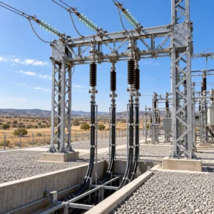
Traction feeders and connections. Medium voltage single-core cable from the traction substation to the catenary, and between sectioning points. Screen bonding, sheath voltage and termination design all belong to this duty, and the standard for the cable follows the system voltage rather than a national habit.
Return path and earthing. Connections from the track to the return conductor, structure bonds and the earthing of lineside equipment. These are short lengths of a heavy section, and they are the ones most often bought late. The verification practice is in our note on grounding and bonding verification.
Signalling, telecom and fibre. The circuits that must keep working while the traction current is running. Immunity is a property of the cable, the screen and the route together, and the screening practice is set out in our note on EMC and cable standards.
Stations, depots and tunnels. Lighting, power, fire alarm, emergency lighting and the tunnel services that have to survive a fire. This is where the fire-rated lines sit, and where the volume of cable in a project usually is.
Cable by Route Section
The table sets out the sections that appear in most mainline enquiries, with the decision each one forces.
| Route Section | What to Declare | Evidence to Ask For | Cost and Lead Time | Risk If Left Open |
|---|---|---|---|---|
| Traction substation to catenary | System voltage, single or three-core, screen bonding, route length | Type test report plus a bonding and sheath voltage note | Medium voltage, longer slot on large sections | Sheath voltage at the termination outside design |
| Sectioning post and cross connections | Current rating, fault level, joint locations, access for maintenance | Short circuit rating and joint schedule | Moderate, joints are the cost | Joints placed where no road access exists |
| Return path and structure bonds | Section, connection points, corrosion at buried joints | Conductor and joint corrosion data | Low cost, high labour | Rail potential above limits at the far end |
| Signalling and telecom route | Immunity requirement, screen type, separation from traction conductors | Screen and earthing details, plus test evidence | Premium on screened constructions | False track circuit occupation in wet weather |
| Station, depot and tunnel | Fire performance, occupancy, escape route, cable penetration sealing | Fire test report naming construction and duration | Fire-rated lines dominate the cost | Handover held up by the fire authority |
Traction Current, Screening and Signalling Immunity
The return path is the noise source. Traction current returns through the rails, and the rails are not a perfect conductor. Some of it goes into the ground, some into structures, and the resulting difference in potential is what a lineside circuit sees as interference.
Screening only works if it is continuous and earthed at the right end. A screen interrupted at a joint, or earthed at both ends of a long run, is worse than no screen in some layouts because it gives the installer a false sense of protection. Write the earthing arrangement on the drawing and check it at commissioning.
Separation is cheaper than screening. Route the signalling cable on the opposite side of the cess, or at a greater height, and the requirement on the cable drops. That is a civil and permanent-way decision taken early, and it is worth arguing for.
Wet weather is when the faults appear. Ballast resistance falls, return current spreads, and track circuits that passed commissioning in summer start to show occupied. Cable specification and route separation both get blamed, and the evidence that settles it is the earthing record.
Long Drums, Track Access and the Installation Window
A joint on a mainline is a possession. Every joint costs a line blockage, a team and a safety plan. That arithmetic is what drives drum length, and it is why a longer drum that is awkward to transport is often the cheaper answer.
Pulling along a cess is not a normal installation. The cable goes into a trough, over short radius bends at structures, and past drainage that is sometimes blocked. Bend radius and sidewall pressure are real constraints here, and they belong in the specification as limits rather than as good intentions.
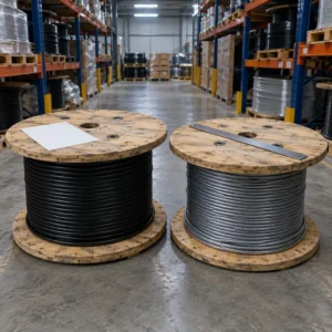
Drum weight has to match the lifting plant. A road-rail machine working in a short possession lifts what it can lift, and a drum that needs a crane turns a two-hour job into a possession with road closures. Ask what the contractor can handle before fixing the drum. The trade is set out in our note on drum length and jointing strategy.
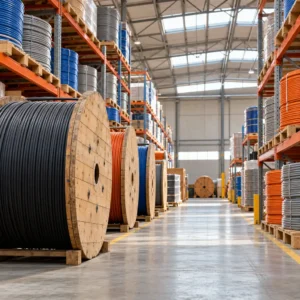
Storage along a linear site is a real cost. Drums spread over a hundred kilometres of route are drums that get damaged, stolen or buried under other deliveries. A single secure compound with scheduled deliveries is duller and cheaper.
Heat, Cold and the Steppe Route
Summer and winter are both design cases. A route across open steppe sees high summer temperatures in the trough and hard frost in winter, and a cable in a shallow trough gets both. Cold bend performance matters as much as the summer rating, and the construction choice is in our note on cold resistant cable.
UV and sand affect everything above ground. Cable rising out of a trough to a structure is exposed, and a sheath that is fine in a plant will crack on a mast in a few years. Specify the outdoor construction where the route leaves the ground.
Armour is a mechanical decision on this route. Rodents, digging, and third-party damage along a fence line are the reasons armour appears in a railway specification, and the selection logic is in our note on steel wire armour selection.
Acceptance, Testing and the Commissioning File
A railway project is audited years after handover. The cable file is what survives: test sheets per drum, joint records with chainage, earthing readings at each bond. A project with good cable and a thin file spends its maintenance budget re-measuring what should have been documented.
Type tests and routine tests are different purchases. A type test report proves the design; the routine sheet proves the drum. Ask for both, and check that the routine sheet names the construction actually supplied rather than the family it came from.
Sampling during production is worth the trip. On a long order, witnessing a sample at the factory is cheaper than discovering at the trackside that the screen coverage is not what the drawing showed. The practice is described in our note on third-party cable inspection.
Commission readings become the baseline. Insulation resistance and continuity recorded at commissioning are the reference for every later test, and without them a slow deterioration looks like a sudden fault. Record them by circuit and by chainage, not by drum.
Railway Cable Order Freeze List
These are the fields to settle before the purchase order is placed.
| Item to Freeze | How to Write It Into the Order | Evidence to Attach | Cost of Leaving It Blank |
|---|---|---|---|
| System and standard | Voltage, standard and conductor class named per circuit | Type test report for the cable class | A cable that cannot be accepted by the traction engineer |
| Screen and bonding | Screen type and earthing arrangement drawn per route section | Bonding diagram with sheath voltage note | Standing voltage at the termination and hot joints |
| Drum length and joints | Drum length set by possession length, joints located by chainage | Drum schedule with chainage references | Extra possessions and a programme slip |
| Signalling immunity | Immunity requirement stated with the separation distance | Screen and earthing details, plus test evidence | Track circuit faults in wet weather |
| Fire-rated circuits | Circuits named, with duration and test category | Report naming construction and duration | Station handover refused |
| Return path material | Conductor and joint material stated, buried joints detailed | Corrosion data for buried connections | Rail potential above limits after a few seasons |
| Environmental rating | Summer trough temperature and winter installation temperature stated | Cold bend and temperature rating data | Sheath cracking at the first hard frost |
When a Standard Power Cable Is Not the Answer
When the cable runs beside the track for its whole length. A power cable in a plant is judged on ampacity and protection. A cable in a railway cess is judged on that plus what the traction return does to it, and the second part is not in a general catalogue.
When the screen is asked to carry current. In some bonding arrangements the screen is a parallel path by design, and its cross section becomes a current carrying decision rather than a shielding one. Say which arrangement you are buying, because the answer changes the product.
When the possession is the constraint. A route that can only be accessed for a few hours a week cannot absorb a joint every drum. If the standard drum length does not fit the possession, the drum is wrong, not the plan.
When the offer quotes a voltage and nothing else. Traction work attracts offers written for general medium voltage supply. Ask for the screen, the sheath, the standard and the test documents before comparing prices, because those four are the whole difference.
RFQ Checklist
- Traction system voltage and standard named per circuit
- Single or three-core decided for every feeder, with bonding arrangement
- Route length and chainage given so drum lengths can be planned
- Possession length stated, so joint positions can be set
- Signalling immunity requirement and separation distance stated
- Screen type and earthing arrangement drawn, not described
- Return path conductor and buried joint details specified
- Fire-rated station and tunnel circuits listed with duration
- Summer trough temperature and winter installation temperature given
- Armour requirement stated with the reason, rodent or mechanical
- Delivery compounds and storage responsibility agreed in writing
Conclusion
Railway electrification cable is bought by voltage class and installed by duty, and the gap between those two views is where projects lose time. The feeder, the return path, the signalling route and the station services are four purchases with four sets of documents. Sort the schedule that way and the specification writes itself; leave it as one line per voltage and the arguments arrive with the first wet autumn.
Kexingyu Cable Group (KXYE) supplies medium voltage single-core and three-core cable, screened signalling constructions, armoured trackside cable and fire-rated station lines from Quanzhou, and quotes railway enquiries section by section with test documents per drum. Send the traction power and signalling schedules with chainage, or upload both. A request for quotation is the fastest way to start, the enquiry format is in our industrial cable RFQ checklist, and bulk ordering into the region is covered in our note on bulk cable orders in Central Asia.