
Specifying a Humanoid Power Harness: Weight, Topology and What to Order
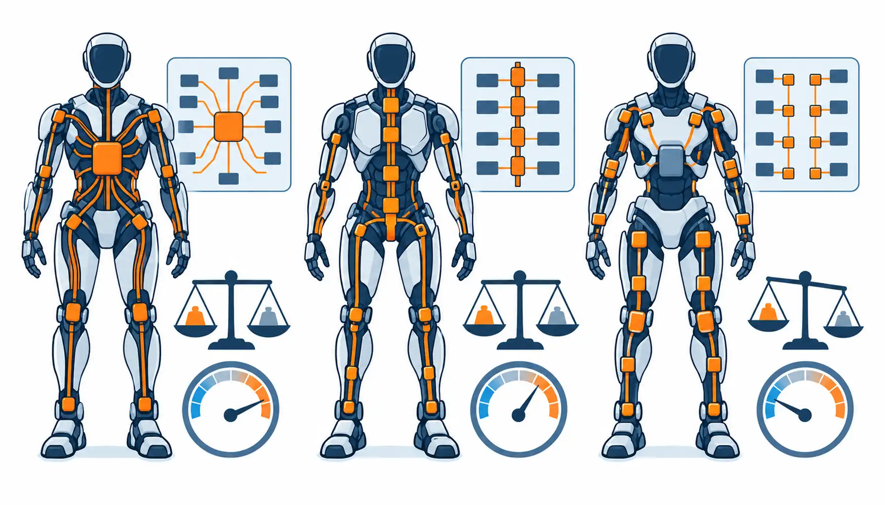
Quick Answer: On a wheeled robot the power harness is dead weight the motors push; on a biped it is weight the legs lift with every step. That single difference decides the architecture. This guide compares the three distribution topologies by copper mass and voltage drop, sets out the evidence to demand from suppliers, and lists the ten decisions to freeze before ordering.
Introduction
High-current battery cabling on mobile machines is usually specified the same way regardless of the chassis, and our note on robot battery cable covers that common ground: current duty, connector temperature rise and abrasion. A humanoid breaks the pattern. The harness runs vertically through a machine that spends its energy budget fighting gravity, so the copper itself becomes part of the locomotion cost.
For procurement, that changes what a good specification looks like. The question is not only “which cable carries the current” but “which architecture carries it with the least mass, at an acceptable voltage drop, with service points where technicians can actually reach them”. Those are architecture decisions, and they belong in the requirement before any supplier quotes a harness.
Why Weight Sets the Architecture
Do the arithmetic once and the priorities reorder themselves. Power conductors sized for peak drive current are the heaviest electrical element in the torso, often outranking the battery management wiring and the signal harnesses combined. Every extra gram of copper sits high on the machine, where it costs the hip and knee actuators torque on every stride and the battery capacity on every shift.
That is why humanoid programs treat harness mass as a specification line with a number on it, not as a consequence of the electrical design. State the budget in kilograms for the complete power harness, distribution hardware included, and require it to be verified by weighing the first article. A calculated estimate hides jacket and connector creep; a scale reading does not.
Weight also changes the routing conversation. On an arm or a torso, a longer route is often the tidy one; on a biped, every extra metre adds mass somewhere the locomotion budget notices. The discipline of stating length, slack and tolerance per run matters more here than anywhere else on the machine, and the method is the same one described in our note on cable length tolerance.
Three Topologies and What Each Costs in Copper
The first topology is a central distribution block: battery to a junction, then dedicated runs to each limb module. It is simple to understand and to service, and every fault is easy to isolate. Its cost is copper, because every limb run is sized for that limb’s peak current over its full length, and the runs to the legs are long by definition.
The second is a spine bus: one heavy trunk running up the torso with tap-off points at each module, rather like the busbar thinking used in fixed installations. The trunk carries the aggregate current and only the tap-offs are sized per limb, which cuts copper mass meaningfully on leggy machines. The trade is serviceability, because a tap-off adds a joint, and joints need strain relief and inspection access.
The third is distributed conversion: a lighter distribution run at higher voltage with local converters at each limb, so the heavy current exists only in short local runs. It minimises copper and keeps voltage drop low, at the price of a converter at every joint and the thermal and reliability questions that follow. Which of the three wins is a function of limb count, peak currents and how often the machine is serviced, and the honest answer for most current programs is a hybrid of the first two.
Voltage Drop Is the Quiet Weight Multiplier
At battery-stack voltages, the current needed by a leg module is high, and voltage drop along a long conductor run is what forces copper area upward. The specification question is how much drop each limb run may lose at peak, and the answer is a real trade: a tight drop figure buys performance at the limb and pays for it in copper the legs carry forever. State the figure per run, at peak current and at the coldest expected start, rather than accepting a generic percentage.
Contact resistance belongs in the same calculation. A topology with more joints spends more of its drop budget at interfaces, where it also generates heat, and the temperature rise at a connector under peak load is one of the few figures that predicts field failures reliably. Demand a temperature rise record for every connector at the declared peak current, and treat a warm joint as a specification failure rather than a normal condition. The thermal mechanics inside enclosed limbs are the subject of our note on thermal paths inside robot arms.
Treat the finished harness as the baseline for that argument. Record the drop of each run and the rise of each joint at commissioning, at a known current, and file the numbers with the harness drawing. Later drift in any of those figures is the earliest warning of a relaxing joint, and it costs nothing to collect if it was specified as a deliverable in the first place.
The Decision Table: Three Power Architectures for a Humanoid
| Architecture | What to specify | Evidence to demand | Cost and lead time | Where it fails |
|---|---|---|---|---|
| Central distribution block | Per-run current, drop limit and the junction rating | A temperature rise record at the block under peak | Lowest design cost, standard lead time | Copper mass that grows with every added limb |
| Spine bus with tap-offs | Trunk rating, tap-off current and joint strain relief | Tap-off pull and thermal records at declared peak | Medium cost, moderate lead time | Frets and hot spots at neglected tap joints |
| Distributed local conversion | Distribution voltage, converter mounting and heat path | Converter thermal records at continuous duty | Highest unit cost, longest integration lead | Converter heat in joints with no airflow |
| Hybrid spine plus local runs | Which segments ride the bus, which get dedicated runs | A mass breakdown and drop map of the full harness | Medium cost, design lead time | Scope creep as exceptions accumulate |
Connectors and Service Breaks in a Weight Budget
The table reads as an architecture choice, but each row is also a procurement package. Whichever row the program picks, the requirement keeps the same shape: mass at finished level, drop at peak per run, temperature rise at every joint, and service breaks at points a technician can reach without stripping the machine. Suppliers can quote against that shape, and quotes become comparable.
What to Freeze Before the Order
Connector hardware is part of the harness mass, and on a humanoid it adds up: a distribution block, tap-offs, module inlets and battery terminations. Choose the smallest connector series that carries the current with margin, and prefer combined power-signal interfaces where a module needs both, because one hybrid joint usually weighs less than two separate ones. The trade-offs of combined interfaces are set out in our note on hybrid connectors.
Service breaks deserve the same discipline as the electrical design. Legs and arms should disconnect at the hip and shoulder, so a limb module swaps without opening the torso; the battery should disconnect at a panel, not behind a frame. Each break is a joint with mass and resistance, so the requirement should name them explicitly, and the bundle discipline that keeps dozens of runs identifiable at those breaks is the one described in our note on multi-axis cable bundle management.
Identification is the quiet half of the service story. A biped carries more power runs than any wheeled machine of similar weight, and at a hip-level break those runs all look alike. Labels at both ends of every run, a schedule that matches the labels, and a rule that no unmarked run ships, cost grams of ink and save hours at the first swap.
When a Lighter Architecture Is Not the Answer
| Item | What to state | Evidence to attach | Cost of leaving it open |
|---|---|---|---|
| Architecture | Which topology the program commits to | A one-line diagram of the distribution | Quotes for three different machines |
| Mass budget | Kilograms for the complete power harness | A weighed first article, hardware included | Torque and range lost to unplanned copper |
| Drop limit | Volts lost per run at peak and coldest start | A drop calculation with conductor areas | Legs that brown-out under peak torque |
| Peak currents | Continuous and peak per limb, with duration | A current profile from the controls team | Conductors sized for a motor datasheet |
| Connector rises | Temperature rise limit at every joint at peak | Rise records at the declared current | A warm joint that becomes a failed one |
| Service breaks | Locations: hip, shoulder, battery panel | A drawing marking each break | Module swaps that require torso surgery |
| Routing path | Run lengths and the slack allocated to each | A routing drawing with tolerances | Mass added by generous, untidy routes |
| Battery interface | Termination type and the disconnect rating | A rise record at the battery joint | The hottest joint hiding at the source |
| First article | Which harness build is the approved reference | A signed first-article report with mass | Production units heavier than the tested one |
| Revision rule | When the harness may be re-spun, and who signs | A change procedure with named owners | Silent mass growth across revisions |
RFQ Checklist
When the program is small and the machine is static for long stretches. A humanoid that walks a few minutes an hour in a demonstration cell is not paying a locomotion tax on its copper, and the simplicity of a central distribution block will beat the mass savings of a bus every time it is serviced.
When the faults are thermal, not structural. If the failure record shows hot connectors rather than excess mass, re-architecting the harness solves nothing. Fix the joint: contact plating, crimp quality and rise limits, whose failure physics are covered in our note on why robot connectors fail.
When the voltage class will change next revision. Distributed conversion and a spun trunk both assume a stable electrical design. If the roadmap moves the stack voltage, buy the tolerant middle path, central blocks with standard runs, and keep the custom architecture for the frozen design.
When the machine already flies close to its mass budget. Then the constraint is real, but the answer is still measured: weigh the current harness, find the grams the drop budget does not need, and recover them run by run. Wholesale re-topology mid-program adds integration risk that no grams-per-kilometre argument repays. Where the overall machine cabling is being standardised, the special wire and cable range is the practical base.
Conclusion
- Distribution topology named, with a one-line diagram attached
- Mass budget in kilograms for the complete harness, verified by weighing the first article
- Voltage drop limit stated per run, at peak current and coldest start
- Continuous and peak currents per limb, with duration, from the controls team
- Temperature rise limit at every connector joint, with rise records at declared peak
- Service breaks located at hip, shoulder and battery panel on a drawing
- Routing drawing with run lengths and allocated slack per circuit
- Hybrid power-signal interfaces listed where modules need both
- First article approved in writing, with mass and drop measurements recorded
- Change procedure for harness revisions, with named approvers


