
Specifying Multi-Axis Cable Management on Robots: Layout, Clamping and What to Freeze
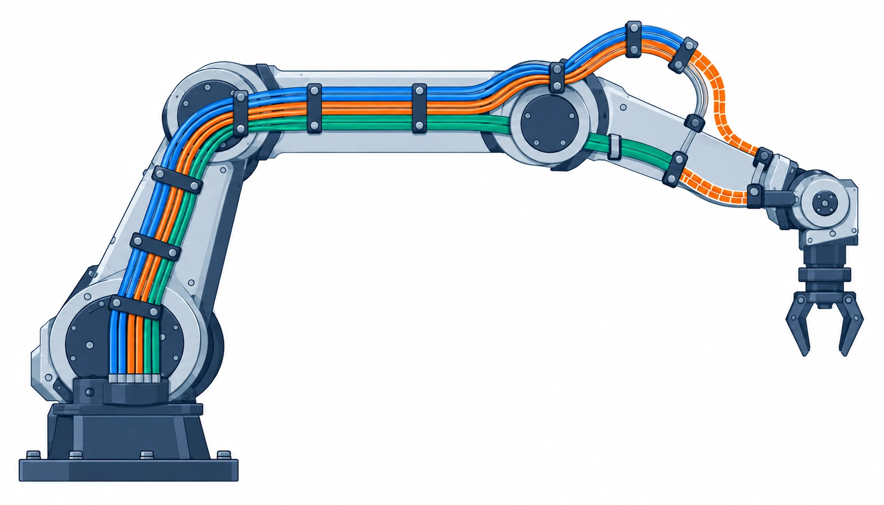
Quick Answer: A multi-axis robot rarely fails because one cable was the wrong grade. It fails because the bundle was never designed. Once power, signal, data and air run together along the same links, the bundle gains its own problems: layers rubbing on each other, a larger overall diameter that pushes the bend radius up, heat that has nowhere to go, and a service visit that starts with untangling. What you specify, and what you get, is the grouping, the route, the clamp positions and the length tolerance.
Introduction
Choosing the cable is the easy part. A continuous flex build, a screened pair, a torsion rated construction, and the right connector on the end, and each cable on its own is sound. The trouble starts when twenty of them share one arm, because the assembly then behaves differently from any of its parts.
The routing of a single run through a joint is covered in our note on cable routing through robot joints. This guide takes the next step up: how to turn a pile of individual runs into a bundle that can be built the same way twice, inspected, and repaired.
Why a Bundle Behaves Differently from One Cable
A single cable in a joint has one motion to survive. In a bundle, every cable is also working against its neighbours. Layers move against each other as the arm moves, and two jackets that rub together wear faster than one jacket against a smooth guide. The wear is hidden inside the bundle, so it is found late, usually as an intermittent fault on one pair rather than as an obvious break.
The second change is geometry. Twenty cables do not sit side by side in a neat row, so the bundle occupies a round section that is larger than any single cable and, more importantly, is stiffer. A bundle has a larger minimum bend radius than its members, and the radius that matters at the joint is set by the whole group. A design that checked one cable against the bend radius and then added nineteen more is a design that will fold the bundle tighter than any of them can take.
The third change is heat. Current in a bundle is shared between conductors that are touching, and the middle of the bundle has no free surface to lose heat from. Derating rules for single cables do not describe a tight bundle in a sealed arm, and the correction factors for grouped runs exist for a reason. Where a dress pack runs in open air, this is a smaller problem, and the comparison between the two is the subject of our note on dress pack cable.
The Layout Rules That Stop a Bundle Fighting Itself
Group by function before anything else. Power with power, screened signal with screened signal, fast data on its own, air and fluid separately. The groups have different bend radii, different noise sensitivity and different service requirements, and separating them at the start costs nothing. What costs money is discovering later that a noisy motor pair is running in contact with an encoder line for the length of the arm.
Then decide where the bundle splits. Every branch point is a fixed point where cables leave the main run for a wrist, a tool or a sensor, and each one needs a defined position and a defined clamp so the split does not migrate. A branch that is left to the build floor moves by tens of millimetres between units, and the cable lengths that were calculated for one layout no longer fit the next.
Bend radius is the third rule, and it is a property of the group rather than of a member. Measure the tightest arc the bundle itself will follow at the joint and state that figure, rather than the catalogue minimum for the largest cable inside it. The mechanics behind that number are set out in our note on cable minimum bend radius, and the same arithmetic applies to a group with a larger factor.
The Decision Table: Bundle Approaches and What Each One Costs
| Approach | What to Specify | Evidence to Demand | Cost and Lead Time | Where It Fails |
|---|---|---|---|---|
| Single combined bundle | Grouping, overall diameter, bundle bend radius and clamp spacing | A flex test on the assembled bundle, not on one cable | Lowest build cost, shortest lead time | Layer-on-layer abrasion found late as one intermittent pair |
| Split groups on one route | Which groups travel together and where they separate | Bend and clearance check at every branch point | Slightly more hardware, same lead time | Loose groups that migrate and rub on the arm |
| Separate routes per function | Two or more routes with their own clamp schedules | A layout drawing showing both routes at full travel | Higher material and assembly cost | Lost savings if the second route was never clamped |
| Composite cable plus tails | Element list, zone separation and tail lengths at each end | Construction data plus a termination first-article | Higher unit cost, longer lead time for tooling | Paying for composite construction where a split bundle was enough |
| Sleeved or wrapped bundle | Sleeve type, coverage, and whether it moves with the bundle | An abrasion test at the real contact points | Low cost, add-on at assembly | A sleeve that traps debris or stiffens the moving section |
Clamping, Spacing and the Section That Moves
Clamps do two jobs: they hold the bundle to the structure, and they decide where the bundle is allowed to move. Space them evenly along the static sections, and stop the schedule short of the joint so the moving section is left free. A clamp placed too close to a moving joint turns a gentle arc into a tight fold at the clamp edge, which is the single most common way a well-chosen cable is destroyed.
The moving section is where the whole design is earned. It needs a defined length, a defined path and enough guidance that the bundle bends where it was meant to rather than finding its own line. Where the run passes inside the structure, that path is fixed by the casting, and the constraints are set out in our note on hollow shaft cable routing. Where it passes outside, the bundle needs guides or a sleeve that follow the motion instead of resisting it.
The transition into a connector belongs to a strain relief rather than to the clamp, and it is the second place where bundles fail early. A bundle entering a connector shell without support loads the contacts with the weight of the whole run, and the mechanics of that interface are covered in our note on strain relief at the connector interface. For the buyer the practical ask is simple: a drawing that shows every clamp, its position and its spacing, with the moving section marked and left clear.
What to Freeze Before the Order
| Item | What to State | Evidence to Attach | Cost of Leaving It Open |
|---|---|---|---|
| Grouping | Which cables travel together and which must stay apart | A group schedule with the noise and voltage reason for each split | A noisy pair sharing a route with a sensitive line |
| Bundle diameter | The overall section, including sleeves and any spare capacity | A drawn cross section at the tightest point | A bundle that fits the drawing and not the casting |
| Bundle bend radius | The radius the group will follow, not the figure for one cable | A flex figure for the assembled bundle | Jacket and screen wear inside the bundle, found late |
| Clamp schedule | Positions, spacing and the marked moving section | A layout drawing with every clamp dimensioned | Movement that migrates onto a sharp edge |
| Branch points | Where cables leave the main run and how the split is fixed | A branch drawing with a clamp at each split | Lengths that fit one unit and not the next |
| Length tolerance | The tolerance on each run and on the bundle as a whole | A first-article measurement record | Loops that build tight on some units and slack on others |
| Identification | Label scheme at both ends and at each branch | A labelling sample on the first article | Service visits that begin with tracing cables by hand |
| Spares route | Any spare core or spare way, and where it is left | A note on the drawing showing the spare | A retrofit that needs a new harness instead of a spare pair |
When a Bundle Is Not the Answer
Where there are only a few runs. Bundling two or three cables adds a sleeve, a clamp schedule and a branch drawing for almost no gain, and each cable is easier to route and replace on its own. The choice between routing inside the structure and running outside it is the subject of our note on internal wiring versus a dress pack, and at low cable counts the simpler route usually wins.
Where high-frequency motion and high cable count meet. A large bundle in a fast-moving joint concentrates bending and heats up in the middle. Where the cycle is fast and the count is high, splitting into two lighter groups that move on separate paths often outlasts one thick bundle, even though it costs more to build.
Where nobody owns the layout. A bundle is defined by its drawing, and a bundle built from memory is a different product on every unit. If the layout cannot be drawn and checked at full travel, the machine is relying on the assembler to invent it each time.
Where abrasion between layers cannot be controlled. If two jackets will rub over a long travel no matter how the run is guided, the answer is separation or a sleeve that moves with the cable, not a thicker jacket on one of them. Where the wear mechanism has already shown up in the field, the patterns are set out in our note on cable damage wear patterns.
RFQ Checklist
- Group schedule listing which cables travel together, with the reason for each separation
- Overall bundle diameter stated at the tightest point, including sleeves
- Bundle bend radius given as a figure for the group, not for the largest member
- Clamp schedule with positions, spacing and the moving section marked as clear
- Branch point drawing showing each split and the clamp that fixes it
- Length tolerance stated per run and for the bundle, with a first-article record
- Label scheme defined at both ends and at every branch point
- Flex evidence requested on the assembled bundle at the real radius and cycle count
- Any spare core or spare way shown on the drawing and carried through the build
- Sleeve or guide specified as a moving part, with a replacement interval if it wears
Conclusion
A multi-axis bundle is a product in its own right, and it is bought on its layout rather than on its cable list. Group by function, fix the branch points, state the bundle bend radius as a group figure, and keep the clamp schedule out of the moving section. None of that is expensive, and all of it is invisible once the arm is assembled, which is exactly why it needs to be on the drawing.
Kexingyu Cable Group (KXYE) supplies the cable side of these bundles: continuous flex, torsion rated and screened constructions, including the special wire and cable range, built so each group keeps its geometry from the reel through to the connector entry. Send us the group schedule, the route and the clamp drawing, and we will return constructions and sample lengths that suit the bundle as a whole; the fastest route is a request for quotation.


