
Robot Motor Cable Temperature: Buying for Heat Inside Enclosed Arms
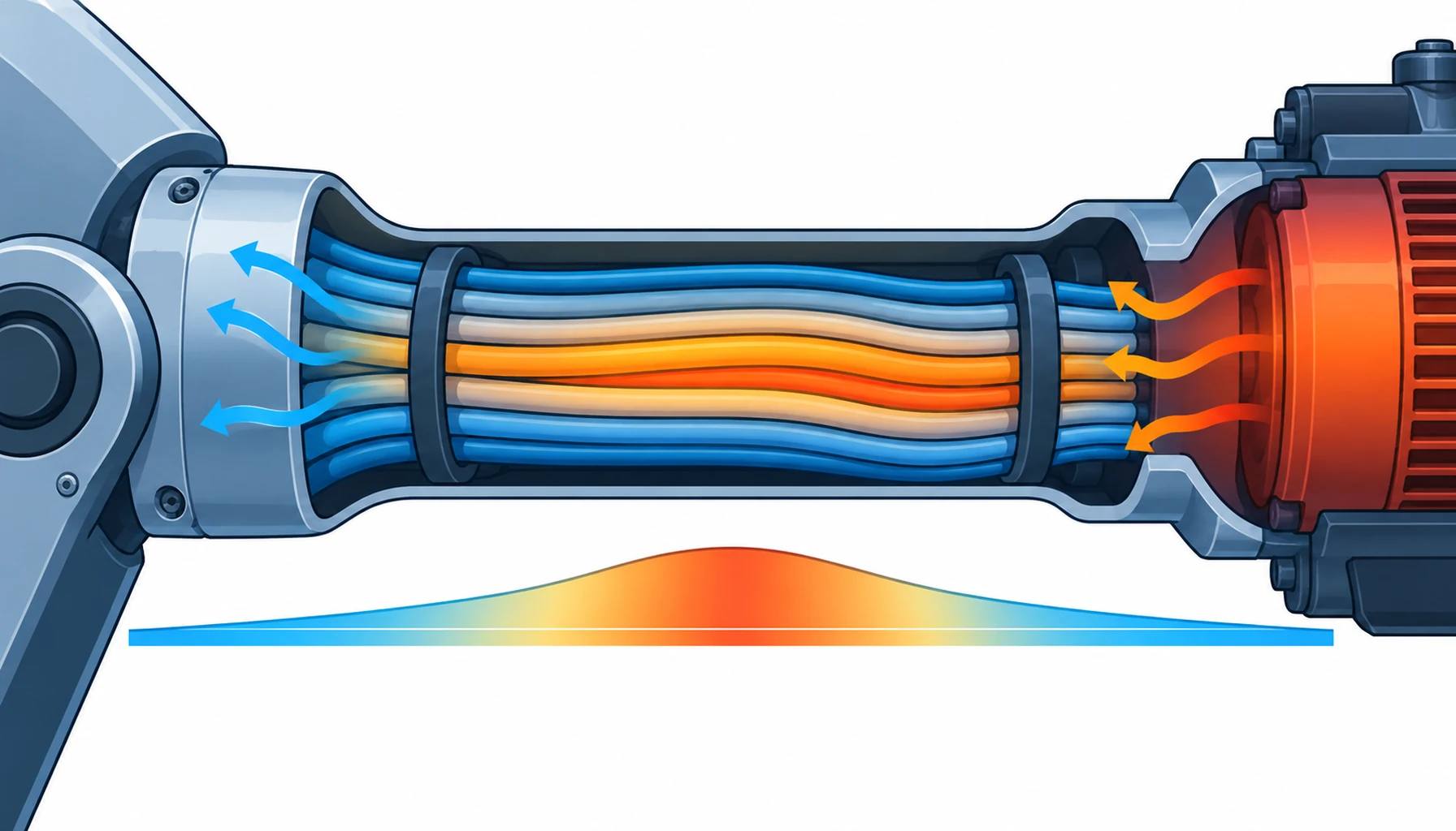
Quick Answer: A motor cable inside a sealed robot link runs hotter than the same cable on a bench, and the gap is not small. Heat comes from the current in the conductors, from the bundle where several loaded cables touch, and from the motor itself. An ampacity figure quoted for a single cable in free air does not describe any of that. What you specify is the conductor size at the real duty, the insulation class, the number of loaded cables in the group, and the temperature rise you are prepared to accept.
Introduction
Motor circuits are sized on current, and current is only half the story. A conductor that carries its rated current in open air can be well over its limit inside a narrow cast link where six other cables are touching it and the only escape for heat is a metal wall. The electrical design looks correct, the cable is within its ampacity, and the insulation still ages faster than anyone planned.
The behaviour of the motor circuit itself, including the drive waveform it sees, is covered in our note on servo cable explained. This guide stays on the thermal side: where the heat comes from, why a bundle changes the answer, and what a buyer can specify and verify.
Where the Heat Comes From
Conductor loss is the obvious source. Current through resistance produces heat in proportion to the square of the current, and a motor cable carries the full motor current rather than a control-level signal. A servo drive also presents a switched waveform rather than a clean sine, and the higher frequency content adds loss in the conductor and, more noticeably, in any screen it passes through.
Terminations add a smaller but useful amount. A contact with high resistance runs warm at its own point, and the heat travels back along the conductor into the insulation. Where a joint has been made with the wrong plating for the current, or where a crimp has been made with the wrong tool, that local heat is the first sign, and the mechanisms are set out in our note on connector contact plating.
The third source is often the largest and is rarely in the calculation. The motor and its gearbox are hot, and the cable that feeds them enters through the same link. Heat travels from the motor frame along the cable and into the conductors by conduction, so a cable that would be comfortable on its own current can be sitting in an environment that starts it twenty degrees higher than ambient.
Why a Bundle Runs Hotter Than One Cable
Heat leaves a cable through its surface, so the surface area of the group is what matters. In a bundle, most of the surface belongs to the outer cables, while the ones in the middle have no free surface at all and can only lose heat through their neighbours, which are also warm. Ampacity tables for cables in free air assume air can reach the whole circumference, and derating factors for grouped cables exist because that assumption stops being true.
Inside a sealed link, a second effect appears: there is no through-flow to carry heat away. A dress pack running in open air loses heat by convection along its whole length, and a motor cable inside a casting does not. The same cable that behaves well outside the arm can be the one that runs hot inside it, and the difference is a property of the enclosure rather than of the copper.
The number of loaded cables matters more than the number of cables. A group where one cable carries motor current and five carry sensing signals is a very different thermal case from a group where four cables are all feeding motors at the same time. That distinction belongs in the enquiry, and it is the same grouping logic that our note on multi-axis cable bundle management applies for other reasons.
The Decision Table: Thermal Options and What Each One Costs
| Option | What to Specify | Evidence to Demand | Cost and Lead Time | Where It Fails |
|---|---|---|---|---|
| Larger conductor | Section sized for the grouped and enclosed condition, not open air | A derated current figure with the basis stated | More copper, slightly stiffer cable, no lead time change | A stiffer cable in a tight link that then fights the bend radius |
| Higher insulation class | Temperature class with the conductor limit, not the class alone | A temperature index or long-term ageing figure | Higher unit cost, longer lead time on specials | Heat that ends at the termination rather than the insulation |
| Separate power and signal groups | Grouping that keeps loaded cables together and away from signals | A group schedule and a layout drawing | More hardware and build time | A gain lost if the groups are re-tied at assembly |
| Metal path for heat | Contact between the cable and a conductive wall or bracket | A temperature rise test with the cable as installed | Low cost, needs design space | Contact that is also a wear point on the jacket |
| Thermally conductive filler | Potting or a filler with a stated conductivity | A supplier figure plus a test on the potted assembly | Higher material cost, service access suffers | Potting that traps heat in the sealed volume instead of conducting it out |
What to Specify and What to Measure
The first specification is the current the cable actually carries, with its duty cycle, at the ambient the link really sees. A motor that runs at full torque for two seconds in a thirty-second cycle does not heat a cable the way a continuous duty does, and a single current figure hides that. State the duty, and let the supplier derate against it rather than against a peak that never lasts.
The second is the temperature class of the insulation, given as a conductor limit rather than as a family name. Two cables in the same class can have very different long-term ageing behaviour, and the difference only matters where the cable is running near the limit for years. Where the environment is hot as well as the current, a high temperature construction is the answer, and the options are set out under our high temperature control cable range.
Verification is the part that is usually missing. A temperature rise test on an assembled link, run at the real duty in the real enclosure, is the only figure that describes the installed condition, and a thermal image of the link at the end of a shift is a cheap way to find the hot spot before it becomes a failure. Where the cable is moulded into a connector, the moulding changes both the heat path and the measurement point, and the trade-offs are covered in our note on overmolded harness assembly.
What to Freeze Before the Order
| Item | What to State | Evidence to Attach | Cost of Leaving It Open |
|---|---|---|---|
| Duty cycle | Current and duration per cycle, not a single peak | A duty profile for the axis | A cable sized for a peak it never holds, or one that overheats |
| Ambient in the link | The temperature the cable really sits in, motor heat included | A measured or estimated figure, not a room figure | A derating calculation built on the wrong starting point |
| Loaded cables per group | How many cables in the bundle carry load at the same time | A group schedule with load marked on it | Relying on a free air figure inside a sealed arm |
| Insulation class | The conductor limit, not only the class name | A temperature index or ageing figure | Insulation that ages early while looking correct on paper |
| Allowed temperature rise | The rise you will accept at full duty, as a number | A rise test at the installed duty | No acceptance criterion, so nothing can be rejected |
| Termination type | Contact, plating and crimp method for the current | A pull-off and a temperature check at the joint | A hot termination that ages the insulation beside it |
| Heat path | Where the cable touches metal and where it is insulated | A layout drawing showing contact points | Heat with no path out of a sealed volume |
| Verification method | Rise test, thermal image or both, and the acceptance limit | A record taken on the first assembled unit | A thermal issue discovered on a machine in service |
When a Bigger Cable Is Not the Answer
Where the heat is coming in from the motor. If the cable is warm because it is bolted to a hot gearbox rather than because of its own current, a larger conductor changes very little. The fix is a thermal barrier or a longer path between the motor and the cable, and the cable size is beside the point.
Where the link simply has no room. A larger conductor is stiffer, and a stiff cable in a short link can force a tighter bend than the route allows. Where the space will not take a bigger cable, the better levers are the number of loaded cables in the group, the insulation class, or a shorter current duty, and the connector end of the same problem is covered in our note on robot harnesses and connectors.
Where the termination is the hot spot. If the temperature rises sharply at the connector rather than along the run, the problem is at the joint, not in the cable. Adding copper upstream of a bad crimp does not lower the temperature at the crimp, and the joint will keep ageing the insulation right beside it.
Where nobody measures the installed condition. A rise test on a bench cable, at a current that is convenient rather than real, answers a question nobody asked. If the acceptance criterion is a bench figure and the machine is a sealed link, the test will pass and the cable will still run hot.
RFQ Checklist
- Current per motor circuit stated with duty cycle and duration, not as a single peak
- Ambient temperature inside the link given, including motor and gearbox heat
- Number of loaded cables in each group stated on the group schedule
- Conductor section justified by a derated figure with the basis written down
- Insulation temperature class given as a conductor limit, with an ageing figure if available
- Termination contact, plating and crimp method specified for the current
- Heat path described, with the points where the cable touches metal marked
- Acceptable temperature rise stated as a number at full duty
- Verification agreed: rise test, thermal image or both, on the first assembled unit
- Thermal barrier or stand-off requested where the cable runs against a hot housing
Conclusion
Motor cable temperature is decided less by the cable than by where it runs. The current is the same inside the arm as outside it, but the surface area, the airflow and the starting temperature are not, and those three are what a derating calculation has to describe. Size the conductor against the grouped and enclosed condition, state the duty and the real ambient, and ask for one rise measurement on the assembled unit. It is a cheap test that answers the only question that matters.
Kexingyu Cable Group (KXYE) supplies the motor and control cables that sit inside these links: screened, continuous flex constructions in temperature classes to suit the enclosure, part of the special wire and cable range, with conductor sizing built to your duty rather than to a catalogue default. Send us the duty profile, the ambient and the grouping, and we will return constructions that hold their rating in the sealed volume; the fastest route is a request for quotation.


