Cable Surge Protection for Industrial Routes: Lightning, Bonding and Checks
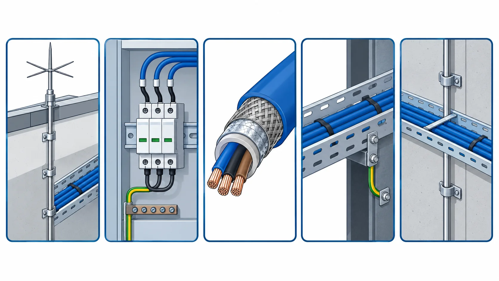
Quick Answer: Most of the cable surge protection on an industrial site is decided long before anyone buys a surge device. Whether a route is shielded, where its armour is bonded, how far it runs from a lightning down-conductor and whether the tray structure is earthed at both ends are all cable and installation decisions, and they decide more of the outcome than the device that gets fitted in the panel afterwards. A surge device on a route that shares a path with a down-conductor is doing less work than the buyer assumes.
Introduction
Surge damage is one of the few cable failures that arrives with no warning and no visible cause. The insulation is intact, the joints are sound, and the cable was fine the day before a storm. The fault then appears at a termination, at a screen, or at the first weak point along the route, and it is usually written up as an insulation failure.
This guide is for buyers specifying cable and cable routes for substations, mine sites, water treatment works, plant rooms and any outdoor installation where a tall structure or an overhead line is nearby. It separates the direct strike case from induced overvoltage, sets out the measures that answer each, the decisions to freeze before the order goes out, and the bonding and inspection checks that hold a scheme together. Screened and armoured constructions for these duties sit in our shielded control cable range, and the standard structure behind them is covered in our note on MV cable standards.
What a Surge Actually Does to a Cable Route
Direct strike current is a different problem from induced voltage. A strike to a structure or an air termination sends a large current to earth through whatever path is available, and the concern for cable is the impulse that couples into it. An induced surge from a nearby strike is a much smaller current at a much higher frequency, and it couples into the loop formed by the cable and its earth return. The two need different answers.
The coupling is magnetic, and the loop area governs it. A cable running beside a lightning down-conductor sees the impulse as a changing field, and the voltage induced in the conductor pair rises with the area of the loop between them. Anything that reduces that loop, such as running phase and earth together or using a screened construction, reduces the surge. Anything that increases it, such as separating the cores from their return path, makes the surge worse.
The failure point is often not the cable. Surges concentrate at impedance changes, which means terminations, screens, joints and the first bend where the screen is broken. A cable that fails after a storm usually failed at an accessory, and the accessory was not chosen for the same duty as the cable.
Repeated low-level surges are cumulative. A device that diverts a modest surge on each storm does its job, but the insulation that absorbs the residual degrades a little each time. That is why a site with poor bonding tends to show a spread of insulation faults over several seasons rather than one dramatic failure.
Protection Measures Compared
The table sets out the measures a buyer chooses between: what each one diverts, what to specify, the evidence to demand, what drives cost and lead time, and how each one fails when it is assumed to cover more than it does.
| Measure | What it diverts | What to Specify | Evidence to Demand | Cost and Lead-Time Driver | How It Fails |
|---|---|---|---|---|---|
| Air termination and down-conductor | The direct strike, keeping the main current away from the cable routes | The separation distance between the down-conductor and any cable tray | A layout drawing with the separation dimension marked at each crossing | Mostly steelwork and installation labour, not cable cost | A tray bolted to the down-conductor path, so the cable takes a share of the strike current |
| Surge protective device at the entry | The residual impulse arriving on the incoming conductors | The device rating, its connection lead length and the required earth reference | Device data plus the installation detail showing the lead length | Device cost is modest; the earthing it depends on is not | Connected with long leads, so the voltage the cable sees is far higher than the rating |
| Screened or armoured construction | Induced overvoltage by reducing the loop area between conductors | Screen or armour type, coverage and how it is terminated at each end | Construction sheet plus the bonding detail at both ends | A modest premium over unscreened cable on the same size | Screen left unbonded at one end, so the induced voltage has nowhere to go |
| Tray and structure bonding | Building a single earth reference along the route | Bonding conductor size, spacing and the continuity across joints | Continuity test results along the whole route | Small material cost and meaningful installation time | A painted or gasketed joint breaking continuity, so the route is earthed in islands |
| Route separation and crossing practice | The coupled impulse, by reducing the loop the strike field sees | Minimum separation from down-conductors and the crossing angle at each intersection | Route drawings with separation distances and crossings marked | Design effort rather than material cost | Cable and down-conductor routed in parallel for a long run, coupling the surge all the way |
Where the Surge Enters and Where the Cable Fails
Most surge entries are through services, not through the sky. An overhead line, a buried duct that leaves the site, or a telecom pair running to an outbuilding all carry the impulse in. That is why the entry point, not the tallest structure, is usually the right place for the protective device.
The screen and the armour are part of the circuit. A screened cable only reduces induction if the screen carries the induced current away, which means it has to be bonded at the ends the design intends. Our note on shielded cable construction covers how the screen is arranged, and the same logic applies to a static route under a storm.
Armour conducts, and that is a feature. Steel wire or tape armour carries surge current and reduces the impulse reaching the cores, provided the armour is bonded at both ends and the bonding survives the mechanical duty. Floating armour, which looks tidier on the drawing, protects nothing.
The earth reference has to be one thing, not several. A route earthed at the building through one path and at the far end through another has a difference in potential across it during a strike, and that difference appears across the cable. The verification method is set out in our note on grounding and bonding verification.
What to Freeze Before the Order Goes Out
Six decisions decide whether a surge protection scheme works as a whole. Each is cheap to settle at specification stage and awkward to retrofit once the tray is up.
| Decision | What to State | Evidence to Attach | Cost of Leaving It Open |
|---|---|---|---|
| Exposure assessment | Whether the site is exposed to direct strikes or only to induced surges from nearby ones | A lightning risk assessment with the strike density for the area | Protection bought for the wrong case, with neither the separation nor the device sized right |
| Entry points | Every service that crosses the site boundary, with the route it takes | A site plan marking each entry and the cable route from it | A device fitted at one entry while the surge arrives through another |
| Screen and armour bonding | Where each screen and armour is bonded, and whether it is one end or both | The bonding detail drawing, plus the continuity test requirement | An electrically floating screen that provides no reduction in induced voltage |
| Separation from down-conductors | The minimum separation distance and the crossing angle at each intersection | Route drawings showing separation at each point where paths converge | A long parallel run beside a down-conductor, coupling the surge into the cable |
| Device and earthing coordination | The device rating, its connection lead length and the earth it references | Device data plus the installation detail and the earth resistance result | A correctly rated device defeated by an installation that adds inductance in its leads |
| Accessories on the route | The termination, joint and gland arrangement, and their impulse withstand | Accessory data with the impulse level, matched to the cable construction | A cable that survives while the accessory at its end is the first thing to fail |
Installation and Bonding Practice
Keep protective device leads short and straight. The connection between a device and the conductor it protects carries the impulse, and its inductance adds to the voltage the cable sees. A device mounted with half a metre of looped lead is protecting at a level far above its nameplate, and the fix costs nothing but a bracket position.
Bond the armour where it can carry the current. Armour and screen bonding needs a proper clamp and a clean metal contact, not a bolt through paint. In a corrosive atmosphere the bonding point should be treated like any other connection in our note on cable sheath materials, because a bonding point that corrodes open is a protection scheme that quietly stops working.
Watch the loop at every cable crossing. Where a cable must cross a down-conductor, a perpendicular crossing is far better than a parallel run, and a short crossing is better than a long one. Draw the angle, because site teams will otherwise take whatever route the tray allows.
Treat EMC and surge as the same problem. Screening, bonding and separation work for both induced surge and ordinary interference, so the two requirements belong on one drawing. Our note on EMC cable standards for machinery covers the steady-state side of the same arrangement.
Incoming Inspection and Site Records
Check the screen and armour continuity on delivery. A screen that is present in the construction sheet but interrupted inside the drum cannot be found electrically after installation, and a continuity check on the delivered length takes minutes. It is the cheapest single check a buyer has on this duty.
Verify separation from the drawing, not from memory. The separation distance that matters is the one on site, and it is worth measuring at the two or three points where the route runs closest to a down-conductor rather than trusting the layout drawing alone.
Record the insulation resistance before and after the storm season. A baseline taken at commissioning separates a surge fault from an installation fault, and the trend across a season is more useful than a single reading. The method is set out in our note on insulation resistance testing.
Keep the earth resistance results with the cable records. The cable cannot do more than the earthing behind it allows, so the earth resistance measurement is part of the cable file rather than an electrical document filed somewhere else.
Cost and Lead Time
Unscreened and unarmoured cable is the cheapest and fastest option and is usually adequate where the route is short and no down-conductor is close. Screened and armoured constructions carry a modest premium on the same conductor size and are mostly stock or short-run items. Specialty jacketed and screened constructions for corrosive or hot sites run to order and belong in the programme.
The larger cost is quite often the installation work around bonding and separation, not the cable itself, which is worth remembering when the protection package is value-engineered. Copper is still the main element of the cable price, so ask how the copper element is calculated and how long the quotation holds. That mechanism is covered in our note on copper price and cable procurement.
When Cable Surge Protection Is Not the Answer
When the failure is not a surge. An insulation fault that appears after rain, or one that follows a load change, is a moisture or a switching problem with a different answer. Blaming the storm is how a real cause stays in service.
When the earthing is the fault. Adding devices to a route whose bonding is broken buys nothing, because the impulse still has no reference to divert to. Fix the earth first, then decide what the device rating should be.
When the route can simply move. A cable run taken off a down-conductor’s path is better protected than the same cable with a device on it, and moving the route costs design time rather than equipment. That is usually the cheapest protection on the whole site.
When the duty is a switching transient, not lightning. VFD switching and capacitor bank operations produce repetitive overvoltages that a single entry device does not address, and the right fix is a filter or a different cable arrangement.
RFQ Checklist
- Whether the site is exposed to direct strikes or to induced surges, from a risk assessment
- Every service entry point, with the cable route taken from it
- Screen and armour construction, with the bonding arrangement at each end
- The minimum separation from down-conductors and the crossing angle at each intersection
- Screen and armour continuity to be verified on delivery, not assumed
- Device rating, connection lead length and the earth reference it depends on
- Earth resistance result for the structure the route is bonded to
- Termination, joint and gland impulse withstand, matched to the cable
- Corrosion protection at every bonding point
- Insulation resistance baseline at commissioning, with the test method
- Marking on the sheath and the construction sheet for the delivered drums
- Copper basis and the validity window of the quoted price
Conclusion
Surge protection on an industrial cable route is mostly a drawing problem. Keep the route away from down-conductors, bond the screen and the armour where the design intends, make the earth one reference rather than several, and fit the device with short leads at the point where the surge actually arrives. Do those four things and the device rating becomes a detail rather than the whole plan.
Kexingyu Cable Group (KXYE) has manufactured cable in Quanzhou since 1996, including screened and armoured constructions for substations, mine sites, treatment works and outdoor process plant, supplied with construction sheets that show the screen and armour arrangement. Send us the site plan with the entries and the routes, and we will come back with the construction, the bonding detail and the tests that apply. A request for quotation is the fastest route.