
PUE and Cabling Losses: What a Cable Specification Can Actually Change
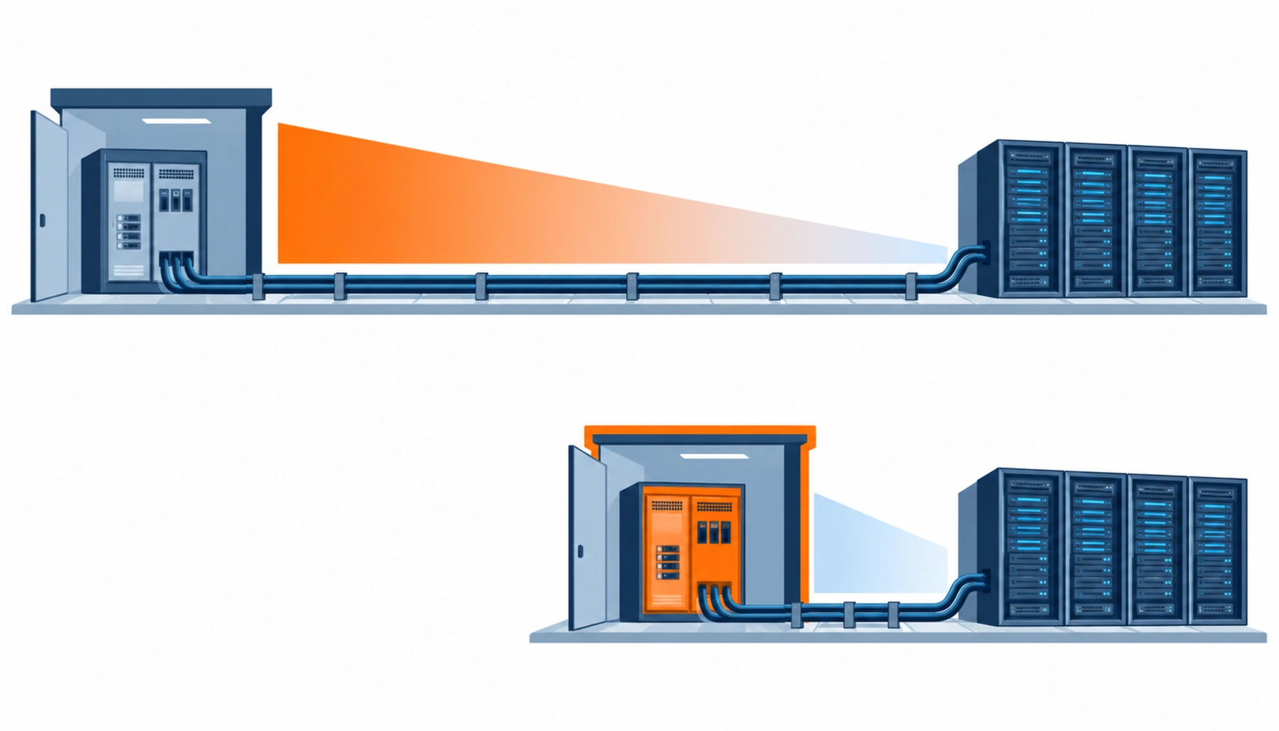
Quick Answer: Cable losses are counted in PUE and they are usually small, because cable resistance is low and distribution runs are short. On a typical hall they account for a fraction of a percent of facility power. That does not make them irrelevant, but it changes what you buy: the measurable wins come from shortening routes, moving the distribution point closer to the load and getting the load factor right, not from specifying the next conductor size up across the whole installation. Calculate the loss before spending money on it, and the specification decisions usually make themselves.
PUE is a ratio, so reducing cable losses improves it in proportion to how much of the total those losses were. Knowing that proportion before designing anything is the whole exercise.
Introduction
Energy efficiency is a procurement driver in data centers, and cable is routinely included in the conversation because it is a passive component that someone can be asked to improve. The trouble is that the improvement is often specified without being quantified, which leads to oversized conductors on short runs and no change at all on the long ones where the loss actually sits.
The honest position is that cable losses matter more in some designs than others. Where distribution sits far from the load, where load factors are high and where routes are long, they are worth engineering. Where the same board feeds racks a few metres away, they are noise. Our note on 415V data center distribution covers the conventional architecture that most halls still use, and the voltage transition covered in our note on the 54V to 800V rack power limit reduces this class of loss as a side effect of a different decision.
Where the Losses Actually Are
Facility power divides into IT load, cooling, and the losses in the electrical distribution itself. The published averages put total facility consumption well above IT consumption: Uptime Institute’s annual global survey has reported average PUE in the 1.5 to 1.6 range in recent years, and the IEA’s estimate of data center electricity consumption sits in the hundreds of terawatt hours annually, which is what makes the fractions worth arguing about.
Within the electrical distribution, the losses split between the equipment and the cable.
Transformers and UPS. The largest share of distribution loss, and the part that efficiency specifications target first. No cable decision changes it.
Switchgear and busbar. Contact resistance, busbar resistance and joints. Small per unit, but concentrated in one place and measurable.
Cable. Resistive loss proportional to current squared. It scales with the square of load, so it falls disproportionately when a hall runs lightly loaded, which is most of the time.
The consequence for a buyer is that cable losses vary enormously between halls. A short-run design at moderate load factor may lose a few kilowatts across the whole site. A long-run design at high load factor may lose ten times that, and it is in that design that conductor sizing is worth calculating.
The Decision Table: Loss Reduction Measures Compared
The table compares the measures usually proposed, priced against the loss each one removes.
| Measure | What to Specify | Evidence You Should Receive | Cost and Lead Time Shape | Failure Mode If Chosen Wrong |
|---|---|---|---|---|
| Larger conductor on long runs | Calculated loss at the actual load profile, not at nameplate current, with the payback period stated | A loss calculation per route showing annual kWh and the incremental cable cost | Modest capital premium; must be decided before the cable is ordered | Upsizing short runs at real cost and no measurable benefit |
| Route length reduction | The position of the distribution board relative to the load, decided at layout stage | Route drawings showing the comparison, with loss calculated for each option | No cable premium; a layout decision that costs nothing but has to be made early | Twenty metres of unnecessary run on every circuit, for the life of the hall |
| Aluminium versus copper | Conductor material with the comparative loss and the installation consequences stated | Loss calculation per option, plus termination and bend radius requirements | Lower metal cost, higher cross section for the same loss | A saving on the cable bill and a loss that cancels it over the operating life |
| Busway instead of cable on long runs | The comparative loss per metre, tap-off allowance, and the future flexibility value | Manufacturer loss figures for the specific rating, plus the cable comparison | Higher capital; the case usually rests on flexibility rather than on loss | Busway chosen for flexibility and justified by a loss figure that was never verified |
| Harmonic and power factor management | Neutral sizing for harmonic load, filter provision, and the measurement method | Power quality survey results and a design that accounts for the measured spectrum | Moderate cost; affects sizing rather than adding a separate asset | Undersized neutral running hot, which is a reliability problem before it is an efficiency one |
Doing the Calculation Before Buying Anything
The calculation is straightforward, and doing it changes most specification arguments.
Resistance. Take conductor resistance at operating temperature, not the 20 °C figure on a datasheet. A conductor running at 90 °C has a resistance roughly 27% higher than at 20 °C for copper, and the loss is proportional to it.
Current profile. Loss goes with the square of current, so an average current matters more than a peak. Use the expected load profile over a year rather than the design maximum, because a circuit at 40% of design current carries only 16% of the full-load loss.
Hours. Multiply by operating hours at that profile. Data halls run continuously, so the annual figure is large even when the instantaneous loss is modest.
Payback. Compare the incremental cable cost against the annual energy saved at the tariff you actually pay, and include the cooling load avoided, since every kilowatt of loss inside the hall also has to be removed. That last adjustment is often the difference between a marginal case and a clear one. Where a project has a stated payback threshold, applying it here settles the argument in a sentence rather than a meeting.
The output of the exercise is a list: which routes are worth upsizing, which are not, and what the difference costs. Where a specification calls for upsizing everywhere, the calculation has not been done. Where it calls for upsizing on three named routes for stated reasons, it has. Our note on the cable size selection guide covers the sizing mechanics that the loss calculation feeds into.
What to Freeze Before the Order
| Item | What to State | Evidence to Attach | Cost of Leaving It Open |
|---|---|---|---|
| Loss calculation basis | Operating temperature, load profile and operating hours used in the calculation | A calculation per route, with assumptions listed | Upsizing decisions made on peak current and never reviewed |
| Routes worth upsizing | The specific routes where the incremental cost pays back, named by circuit | A ranked table of routes by annual loss | Whole installations upsized, with the cost spread evenly and the benefit concentrated nowhere |
| Conductor material | Copper or aluminium, with the comparative loss and the termination implications | A comparison table per route, including installation consequences | A material substitution that saves on the invoice and loses in operation |
| Neutral sizing | Neutral sized for harmonic content, with the assumed spectrum stated | A power quality survey or a stated assumption with its basis | A neutral that runs hotter than the phases and fails first |
| Payback criterion | The payback period that justifies an upsizing decision, agreed before the tender | A written criterion applied consistently across routes | Inconsistent decisions that cannot be defended in a design review |
| Board positions | The electrical room layout and board positions, with route lengths calculated from them | Layout drawings showing the runs used in the calculation | Layouts changed later, invalidating the loss case and lengthening every run |
| Measurement provision | Whether losses will be measured after energization and with what instrument | A metering provision in the board and a measurement plan | A design intent that is never verified, and an efficiency claim that cannot be evidenced |
| Documentation | The loss calculation issued with the as-built package, with assumptions stated | A calculation file issued as an editable document, not a PDF summary | A future retrofit that repeats the analysis from scratch |
When Buying Efficiency Through Cable Is Not the Answer
Where the runs are short. In a hall where boards sit within a few metres of the racks they feed, cable loss is too small for upsizing to pay back inside the life of the installation. Spending there displaces money from measures that do move PUE.
Where the load factor is low. Loss scales with the square of current, so a lightly loaded hall has very little cable loss to remove. Where utilisation is expected to stay below half of design capacity, the efficiency case for larger conductors largely disappears.
Where cooling is the dominant term. PUE is dominated by cooling in most halls. A cable programme that improves PUE by a small fraction of a percent is competing with improvements that move it by whole points, and the comparison should be made explicitly rather than assumed.
Where the driver is a reporting target rather than a cost. Where the objective is an efficiency metric for reporting, the most reliable improvement usually comes from measurement and load management rather than from copper. Our note on data center power demand growth covers the demand side of the same picture.
RFQ Checklist
- Loss calculation for each route, at operating temperature and on the actual load profile
- Assumptions listed explicitly: temperature, load profile, operating hours and tariff
- Routes ranked by annual loss, with the upsizing case made only where it pays back
- Payback criterion agreed before the tender and applied consistently
- Cooling load avoided included in the benefit side of the calculation
- Conductor material comparison per route, including termination and bend radius consequences
- Neutral sized for the assumed harmonic spectrum, with the basis stated
- Board positions fixed before route lengths are calculated, with layout drawings attached
- Metering provision included where post-energization loss measurement is required
- Loss calculation issued with the as-built package as an editable document
- Any efficiency claim in the tender supported by a calculation, not by a specification statement
- Busway options compared on loss and on flexibility separately, with both figures shown
Conclusion
Cable losses deserve to be calculated rather than assumed, and the calculation usually shows that the win is in route length and load profile rather than in conductor size. Where the numbers support upsizing, buy it on the routes where it pays and leave the rest alone. Where they do not, the honest position is that the efficiency budget is better spent on cooling, on power quality or on a distribution layout that shortens the runs in the first place.
Kexingyu Cable Group (KXYE) supplies the cable that this analysis sizes, including the WDZ-YJY, WDZN-YJY, BTTZ, NG-A (BTLY), KVV and YJV ranges, the data center cable range used on submain and riser routes, and the multi-purpose distribution cable used on distribution circuits, from one factory group with copper price linkage on project-scale orders, so the incremental cost of a larger conductor can be quoted precisely for the routes where the calculation supports it. Send your routes and load profile and we will return the resistance and rating data needed for the loss calculation; the fastest route is a request for quotation.


