Site Temporary Power Distribution: Specifying Boards, Feeders and Final Circuits
Quick Answer: Temporary power on site is a hierarchy: supply point, main boards, zone or floor sub-boards, and final circuits. Each level buys different cable, and most site power problems trace back to one level being specified like another. Select armoured feeders for the long runs, heavy rubber connecting cable between boards, standardised flexible cord at the workface, and make the voltage drop calculation part of every quotation.
Introduction
Site power gets rebuilt every few weeks. The building grows, boards move up a floor, feeders are re-routed around the crane base, and every reconfiguration is an installation done quickly, in work boots, by crews who are also doing everything else. Temporary distribution has to be designed for that reality, not for a switchroom.
The procurement consequence is simple: the specification has to work when it is installed fast and reconfigured often. That pushes the decisions into standardisation and sizing discipline rather than exotic hardware, and it is why the hierarchy, level by level, is the right way to buy.
The Hierarchy: Why Level by Level
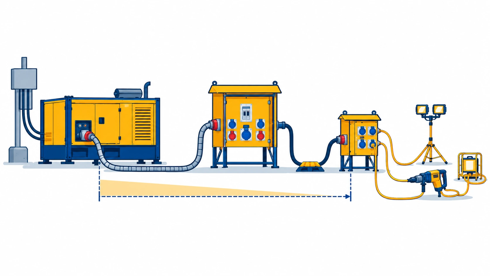
The supply point, main boards, sub-boards and final circuits exist to keep faults small. A fault at a tool should trip the board at the workface, not the site. That principle, embodied in the three-level construction distribution box approach, is also a cable selection principle: each level has its own duty, its own construction and its own failure mode.
Level one: the supply point. Where the site takes supply from the network or its own generation. The cable here is armoured feeder to the main boards, sized generously, because everything downstream depends on it.
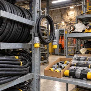
Level two: distribution. Main boards to zone or floor sub-boards, moved and reconfigured as the build grows. Heavy rubber connecting cable, sized with headroom, is the standard tool.
Level three: final circuits. Sub-board to tools, pumps and lighting. Flexible cord and extension leads, standardised across the site so inspection is fast.
Armoured Feeders: The Long Runs
The feeders that cross the site are the backbone, and two decisions dominate their specification.
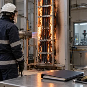
Armoured or not. Buried runs and anything exposed to plant traffic takes armour; runs clipped to the structure at height, protected from impact, can sometimes go unarmoured and save money. The decision is exposure, and our comparison of armoured versus unarmoured cable gives the criteria. What never works is armour chosen as a substitute for routing: a feeder laid across a haul road fails whatever it is wearing.
Sizing on voltage drop. Site feeders are long and the load sits at the far end, so voltage drop, not ampacity, usually decides the conductor. Give the supplier the measured route, the running and starting currents, and ask for the calculation with the quotation. The transformer or substation option at the head of the system, covered in our note on transformers and substations for site supply, is often cheaper than fighting a long low voltage run.
| Level | Duty | What to Specify | Evidence to Demand | Cost and Lead-Time Driver | How It Fails |
|---|---|---|---|---|---|
| Supply point to main boards | Fixed per phase, buried or on route, high load | Armoured feeder sized on voltage drop, drum lengths to pulling sections, sheath for burial or surface, glands and earthing | Voltage drop calculation, conductor resistance records, sheath and armour drawings | Copper content dominates; drum logistics and pulling gear | Damage at backfill and crossings, water in a cut sheath, undersized conductor at the far end |
| Main boards to sub-boards | Reconfigured as the build grows, handled between phases | Heavy rubber connecting cable sized with headroom, plug-compatible ends, lengths that reach without joints | Flex and abrasion data, water resistance, continuity per length | Stock lines; headroom costs copper now and saves re-orders | Cuts at crossings, crushed sections, joints landing in wet corners |
| Sub-boards to workface | Final circuits, re-laid weekly, inspected constantly | Flexible cord and extension leads, standardised lengths and connectors, ratings matched to the tools actually used | Standard certifications, inspection compatibility | Volume item; standardisation beats unit price shopping | Nicks and exposed conductors, failed mouldings, improvised repairs |
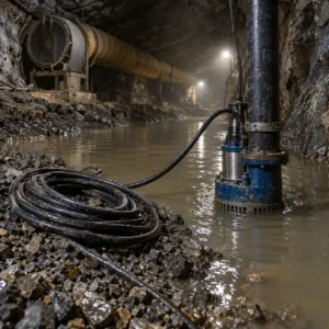
| Special circuits: pumps, welders, site offices | Continuous or heavy loads at specific positions | Sized per load with duty stated, water-resistant construction for pumps, dedicated circuits rather than shared boards | Duty cycle and sizing notes, water resistance for pump circuits | Small share of the order, disproportionate share of the faults | Overloaded shared circuits, pump cables in standing water on undersized cores |
Between Boards: The Rubber Cable Standard
Board-to-board runs are the level most worth standardising, because they are the ones crews reconfigure. A heavy rubber connecting construction, in two or three standard sizes with compatible plugs, covers almost every run; the heavy yellow rubber connecting cable class exists for exactly this duty, and splash-resistant constructions handle the wet corners of the site. Our note on splash-resistant rubber cable covers the wet-work variants.
Standardise three things across the site: sizes, lengths and connectors. Standard lengths mean runs join at boards instead of mid-air; standard connectors mean any crew can reconfigure any run; standard sizes mean the spare stock actually fits the job that needs it.
Final Circuits: The Inspection Surface
Tool leads and flexible cord are the most inspected items on any site and the cheapest in the order. Standardising them is a procurement decision with safety returns: one cord specification, one colour scheme, one length range, and a ban on home-made repairs enforced by a swap-out stock of tested leads. Where the cord leaves the board into wet or outdoor positions, the flexible cord and cord set options need matching to the exposure, because an indoor cord on a roof is the first thing an inspection fails.
Generators and the Supply Point
Where the site generates its own supply, the supply point is a generator bay, and the cabling between sets, changeover and main boards follows its own rules; our note on generator ATS cable connections covers the connections that fail there. The same level-by-level discipline applies downstream, and the generator bay is where earthing and the supply point’s protection settings are settled together.
Protection Coordination on Temporary Systems
Temporary distribution earns its keep in how it trips, and coordination is a procurement input, not just an engineering one.
Faults stay small. The hierarchy only protects the site if each level’s protection is set above the level below it, so a tool fault opens the workface board alone. State the protection scheme per board in the order, and buy boards and cable from one source where possible so the settings arrive consistent with the design.
Earth fault and RCD levels. Wet sites push residual current protection down to the workface, and the cords and connectors on those circuits must suit the devices protecting them. A final circuit whose construction leaks to earth in the rain trips a healthy system all day; ask for the leakage behaviour of the outdoor constructions being quoted.
Settings travel with the boards. Temporary boards move and get re-energised by whoever is standing there. Put the settings schedule in the delivery documents, laminated and dated inside the board door, and the coordination survives the crew turnover that would otherwise erase it.
Weather, Positioning and Reconfiguration Discipline
Temporary systems live outdoors by definition, and most of their life is weather. Three disciplines decide whether the hardware lasts the build.
Position the boards above the water. Every board stands on a plinth or stand, clear of standing water and wheelbarrow routes, with cable entries from below. Half the water-related faults on site power are boards standing in puddles that a five-minute positioning decision would have avoided.
Route the cable where traffic is not. Feeder and connecting cable routes belong behind barriers, overhead where possible, and across traffic only at protected crossings. The routing drawing is part of the order documents for exactly this reason.
Reconfigure by the standard. When the build moves a board, the re-lay uses the same lengths, connectors and tagging as the first installation. Reconfiguration done to the site standard keeps the system inspectable; reconfiguration done in a hurry is how a tidy phase one becomes an untidy phase three.
What to Freeze Before the Order
| Decision | What to State | Evidence to Attach | Cost of Leaving It Open |
|---|---|---|---|
| Level map | Boards, positions and reconfiguration phases for the build | A single line diagram with board positions by phase | Cable bought per job instead of per hierarchy |
| Feeder sizing basis | Measured routes, running and starting current, diversity | Voltage drop calculation per feeder | Brownouts at the far boards and a re-order |
| Armour and routing | Exposure per run: buried, traffic, structure-mounted | Routing drawing with protection noted | Feeders failed by the route they were given |
| Rubber cable standards | Sizes, lengths and connectors standardised site-wide | A one-page site standard with the plug list | Runs joined mid-air and stock that fits nothing |
| Final circuit specification | Cord sizes, colours and lengths, with the repair policy | The site standard as issued to crews | Inspection findings on non-standard leads |
| Copper basis on feeders | Basis, validity window and revision rule | Quotation terms naming the basis | A supply point priced months before the order |
Lead Time and Cost Structure
Temporary distribution is a fast line by construction standards. Armoured feeder is made to order in one to three weeks against drum lengths; rubber connecting cable, flexible cord and boards are stock. The discipline is sequencing: feeder drums arrive before the supply point is built, and the board stock lands with the site establishment rather than after the first reconfiguration exposes the gap. Confirm both dates at order, because the supply point is built once and the first reconfiguration is already on the programme.
On cost, copper dominates the feeder line, and the connecting cable stock is a working capital decision: the right two or three sizes held in depth beat six sizes held thin. Fix a copper basis with a validity window on the feeder order, because the supply point is designed at tender and bought months later. Our note on cable price breakdown shows what sits inside each unit price besides metal.
Incoming Inspection
Feeders. Check drum lengths and markings against the pulling schedule, photograph the markings, and run conductor resistance and insulation tests before the drum is pulled. Verify the armour and sheath construction on a sample against the order.
Connecting cable and cords. Check lengths and plugs against the site standard, and continuity per length. Put the inspection tags on at the gate, not after the first use on site, so every run in service is traceable to a tested length.
When a Temporary Power Specification Is Not the Answer
When the voltage drop is a layout problem. Oversized feeders bought to push power to a badly placed board is the expensive fix. Moving the board, or stepping the voltage down closer to the load, is often cheaper than the copper.
When the faults are reconfiguration damage. Connecting cable failing after every move is a handling and storage issue. Drum racks and a re-lay routine cost less than replacing jackets.
When the site standard has drifted. If inspections keep finding odd lengths and mismatched plugs, the problem is the standardisation discipline, and no cable specification repairs it.
When the load has outgrown the design. A site that added a batching plant or a second crane has a new supply problem. Re-derive the hierarchy rather than loading the existing feeders past their calculation.
RFQ Checklist
- Single line diagram with board positions by build phase
- Feeder routes measured on site, with running and starting currents
- Voltage drop limit per feeder, with the calculation expected from the supplier
- Armour and routing decision per run, with exposure stated
- Drum lengths matched to pulling sections, with handling limits
- Standard sizes, lengths and connectors for connecting cable, site-wide
- Cord and extension lead specification, with the inspection regime
- Special circuits: pumps, welders, offices, sized per load
- Test records per drum and per length, with inspection tagging
- Copper basis with validity window on the feeder order
Conclusion
Temporary power is bought well as a hierarchy: armoured feeders sized on honest voltage drop, rubber connecting cable standardised across the site, and final circuits treated as the inspection surface they are. Freeze the level map and the sizing basis with the order, re-derive the hierarchy whenever the load changes, and the site’s power stops being a weekly emergency.
Kexingyu Cable Group (KXYE) has manufactured cable in Quanzhou since 1996, including armoured feeder, heavy rubber connecting and flexible cord constructions for temporary site distribution, alongside the distribution equipment they feed. Send us the single line diagram and the board schedule, and we will come back with constructions per level, the calculations and a delivery sequence against your build phases. The fastest route is a request for quotation.