
Tendon-Driven Actuation: When the Cable Is the Motion Element
Quick Answer: In a tendon-driven robot the cable is not wiring, it is the actuator, and it fails like a structural part: by fatigue, stretch and abrasion at the sheaves. This guide sets out the tensile and cycle evidence to demand, the sheave geometry to check before the order, and the ten decisions to freeze.
Introduction
Everywhere else in this series, cable carries signals and power while the structure moves. Tendon-driven actuation inverts the arrangement: a slim cable or cord transmits force from a remote actuator to a joint, the way a brake cable or a bowstring works, and the machine’s motion quality lives and dies on that element. Humanoid hands in particular have embraced the approach because it lets the motors sit in the forearm, far from the fingers.
For procurement, the inversion matters because the specification changes category. A transmission tendon is bought the way a machine element is bought: with load ratings, fatigue evidence, wear prediction and a replacement interval. The electrical habits of mind, voltage drop, shielding, continuity, barely apply, and treating a tendon like a cable is how programs end up with a motion element that was never actually specified for motion.
What Tension Cycling Does to a Tendon
A tendon lives in tension, sometimes millions of cycles of it, and the failure modes are structural. Fatigue breaks load-bearing filaments one by one, so strength decays gradually and invisibly; stretch accumulates as the construction beds in, loosening pre-tension and adding backlash at the joint; and creep, a slow permanent elongation under sustained load, shifts calibration on machines that sit loaded between tasks. None of these announce themselves the way an electrical fault does.
The material choice sets which mode dominates. Ultra-high-molecular-weight polyethylene cores, the Dyneema-class fibres, offer outstanding strength for their weight and low friction, but they creep noticeably under sustained load. Aramid cores resist creep and heat far better at the cost of lower flexibility and careful handling. Steel cores resist creep almost completely and tolerate tight sheaves, at a weight and friction penalty that matters in a hand. The right answer is duty-specific, and the requirement should say which mode the application fears most.
Count the duty in the tendon’s own terms: peak tension, mean tension, cycles per hour, and the sheave diameter it bends over at each pass. Those four numbers, more than any datasheet adjective, determine which constructions can actually survive the application, and they belong in the RFQ as figures. Where the same element also carries sensor channels, the problem compounds, and the wiring side is handled in our note on dexterous hand wiring.
Sheaves: Where Tendons Actually Die
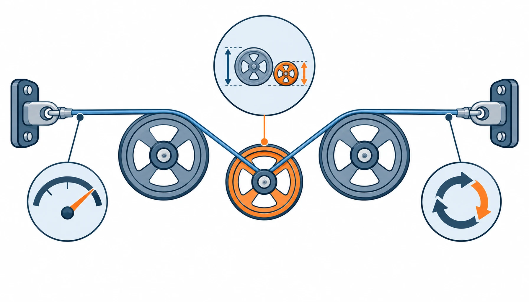
A tendon rarely fails mid-span. It fails where it bends, which means the sheave train is part of the tendon specification whether the drawing admits it or not. Bending a tensioned element over a small diameter works the outer filaments hard at every pass, and the ratio of sheave diameter to tendon diameter is the single most predictive geometric number in the system. Bigger pulleys cost envelope and mass; smaller ones cost cycle life. State the minimum ratio the design can offer, and demand fatigue evidence at that ratio rather than at a flattering one.
Surface finish and alignment matter nearly as much. A rough groove acts as a file under tension, a misaligned sheave rubs the tendon against its flange, and both consume life faster than the material choice does. The inspection routine should therefore cover the sheaves and the tendon together, because replacing tendons while running worn grooves simply restarts the clock on the same failure. Abrasion testing methodology for exactly this kind of contact is set out in our note on the cable abrasion test standard.
Jackets complicate and protect at the same time. A jacket shields the load-bearing core from groove wear and keeps fibres from unlaying, but it adds diameter, which worsens the effective bend ratio, and a stiff jacket can hold the core against the groove unevenly. The jacket choice deserves the same evidence-based treatment as the core, and the material options are compared in our note on abrasion resistant cable jackets.
The Decision Table: Tendon Constructions Compared for Procurement
| Construction | What to specify | Evidence to demand | Cost and lead time | Where it fails |
|---|---|---|---|---|
| UHMWPE fibre core | Tensile rating, creep class and the sheave ratio | Cycle records at your load and ratio | Medium cost, short lead time | Creep on machines left under load |
| Aramid core | Tensile rating, bend diameter and handling rules | Cycle records plus a handling note in the delivery | Medium cost, short lead time | Kink damage from rough handling |
| Steel-cored tendon | Construction class, pre-tension band and lubrication | Fatigue records at the smallest sheave | Lower cost, standard lead time | Weight and friction in dynamic joints |
| Jacketed composite tendon | Jacket material, diameter tolerance and the core ratio | Abrasion and cycle records on the finished tendon | Higher cost, custom lead time | Jacket wear hiding core damage |
Stretch, Pre-Tension and the Adjustment Budget
One row is not better than another; each buys a different compromise. What they share is the evidence structure: cycle records at the declared load and sheave ratio, tensile certification, and a stated pre-tension band. A tendon quoted without those three items has been priced, not specified, and the difference shows up in the replacement schedule.
The Drive Path and the Bench Test That Qualifies It
Every tendon system stretches a little when it beds in, and the design needs an adjustment budget: an idler or tensioner with enough travel to take up the initial elongation and the slow growth after it. The requirement should state the expected elongation over the first thousand cycles and the adjustment mechanism that absorbs it, because a system with no take-up converts normal bedding into permanent backlash and a warranty claim.
Pre-tension is part of the same conversation. Set it too low and the tendon skips or slaps under load reversal; too high and every sheave pass works harder than the fatigue evidence assumed. State the band, the gauge method and who checks it, at assembly and at each service. Where positioning accuracy matters over months, prefer the low-creep constructions from the start rather than recalibrating around drift, and treat elongation as a maintenance signal rather than a nuisance.
Inspection closes the loop. Elongation against a datum, visible filament breaks, jacket wear at each sheave and the sheave grooves themselves make a five-minute visual and mechanical routine per unit, done on a stated interval. The wear signatures worth learning are catalogued in our note on cable damage wear patterns, and they read the same on a tendon as on any flexible element, only faster.
What to Freeze Before the Order
A tendon is only as predictable as its path. Every extra sheave adds friction and two more bend cycles per motion, every direction change adds wear concentration, and the total path length sets how much the element stretches under load. So the routing drawing deserves the same procurement attention as the material choice: count the sheaves, mark the direction changes, and ask whether the last two are earning their keep. Programs that tidy the path before buying the tendon usually find they can use a smaller, cheaper element at a gentler ratio.
Qualification then belongs on a bench that reproduces the path. A short rig with the real sheave diameters, the real load profile and the declared cycle rate tells you more in two weeks than any datasheet comparison, and it doubles as the reference for the wear inspection routine later. Flex testing methodology for exactly this kind of rig is set out in our note on cable flex testing methods, and the sample build that feeds it is covered in our note on robot cable sample testing.
Write the bench result into the file. A tendon with a passed cycle record at the true geometry, filed beside the load profile and the sheave drawing, gives the program a defensible replacement interval and gives the supplier a target to hold. Skipping the bench saves a fortnight now and buys a field failure whose root cause nobody can isolate, because every element in the path was plausible in isolation.
When Tendon Drive Is Not the Answer
| Item | What to state | Evidence to attach | Cost of leaving it open |
|---|---|---|---|
| Peak and mean tension | Newton values with duty cycle, per tendon | A load profile from the controls team | A tendon sized by feel |
| Sheave ratio | Minimum sheave-to-tendon diameter in the design | Fatigue records at that exact ratio | Fatigue life spent at the grooves |
| Core material | Which failure mode the application fears most | Creep and cycle data per candidate | Backlash that appears after bedding-in |
| Cycle count | Cycles per hour and the design life in hours | A cycle record at declared load and ratio | Replacement interval nobody can defend |
| Jacket | Material, diameter tolerance and its effect on ratio | Abrasion records on the finished tendon | Core wear hidden until failure |
| Pre-tension | Band, gauge method and check interval | A written setting procedure | Slap, skip or overload, depending on luck |
| Take-up travel | Adjustment range for bedding and growth | A drawing of the tensioner | Backlash with nowhere to go |
| Anchors | Termination type and pull-out rating | Pull test records per anchor type | The strongest tendon failing at its knot |
| Inspection routine | What is checked, at what interval, by whom | A checklist agreed at commissioning | Gradual decay read as sudden failure |
| Spares | Complete tendon sets held per machine | A spares list with revisions | A machine benched for one cord |
RFQ Checklist
When the joint needs stiffness in both directions. Tendons pull, they don’t push, and antagonist pairs or push-rods carry the return. Where a joint demands high two-way stiffness with minimal compliance, a direct drive or a push element beats any tendon arrangement, and no tendon specification will change that.
When the duty is light and the machine is a demonstrator. A scripted demo hand sees a fraction of field tension cycling, and a fully qualified tendon programme spends money on evidence the duty will never test. Buy reputable standard cord, set the pre-tension, hold spares, and spend the engineering hours elsewhere.
When the failures sit at the grooves. If wear concentrates on sheaves and flanges, new tendons inherit the same death. Re-machine or replace the pulley train first, then judge the tendon. The same logic applies on any flexing system, as our note on robot cable failure describes for the electrical cousins.
When creep would corrupt the measurement. Machines that hold position under load between uses, gauging rigs and assembly fixtures among them, will drift on polymer cores no matter how good the fibre. That is a physics problem, not a quality problem, and the honest answer is a low-creep core or a different mechanism. Where the qualification evidence itself is the question, our note on humanoid cable test standards covers what can be tested and what has no standard yet.
Conclusion
- Peak and mean tension with duty cycle stated per tendon
- Cycles per hour and design life in hours declared
- Minimum sheave-to-tendon diameter ratio stated, with fatigue records at that ratio
- Core material chosen against the dominant failure mode, with creep and cycle data
- Jacket material and diameter tolerance stated, with abrasion records on the finished tendon
- Pre-tension band, gauge method and check interval written into the order
- Take-up travel dimensioned for bedding-in and long-term growth
- Anchor terminations with pull-out test records per type
- Inspection checklist agreed at commissioning, covering tendons and sheaves
- Spare tendon sets held per machine, built to the approved revision


