
Insulation Resistance Testing Before Energization: Continuity, Pass Criteria and What to Record
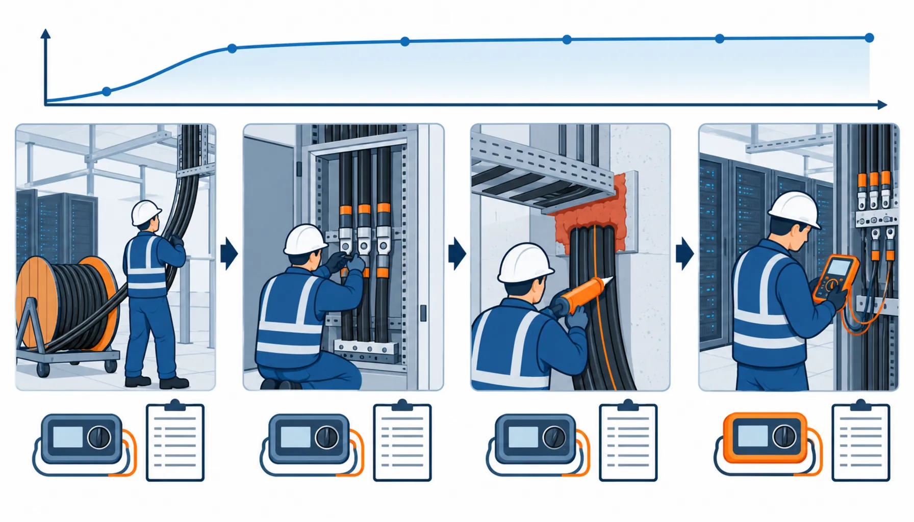
Quick Answer: An insulation resistance test costs almost nothing to perform and is worth almost nothing without context. A reading is only usable if the test voltage is appropriate for the circuit, the instrument calibration is in date, the temperature and humidity are recorded, and the number is compared against a commissioning criterion rather than against the code minimum. The values in the installation standard are a safety floor, not an acceptance standard, and a new cable that just clears the floor is a cable that warrants investigation rather than sign-off.
Pre-energization testing is the last opportunity to find a problem while nothing is live. Everything after that point is done on energised equipment, under outage pressure, with the hall already handed towards operations. That is the argument for treating the insulation and continuity tests as a defined deliverable with a defined evidence format rather than as something the electrical contractor does on the way through.
Introduction
The two tests that matter before energization are usually discussed as one activity and they are not. An insulation resistance test measures the resistance between conductors and earth, and its purpose is to demonstrate that the insulation is intact. A continuity test measures the resistance of the protective conductors and the bonding path, and its purpose is to demonstrate that a fault will find a path back to the source so that the protective device operates. One test proves that the system will not fail by leakage. The other proves that it will fail safely. Both are needed, and neither substitutes for the other.
The commercial angle is that both tests are cheap and both produce evidence that a project will need later. A complete set of per-circuit records, taken with a calibrated instrument and dated, is what allows a defect found during the warranty period to be attributed. A set of readings that says “tested, pass” with no instrument reference and no conditions is worth nothing in that conversation, because there is nothing in it to check. The surrounding commissioning evidence is covered in our note on TIA-942 certification testing.
What the Test Proves and What It Cannot
Being precise about scope keeps the specification honest.
What it proves. That the insulation between live parts and earth, and between live parts, has a resistance above the value you specified, measured at a voltage you specified, with an instrument whose calibration is in date. Applied at the right point in the sequence, it catches cable damage from installation, moisture ingress, incorrect terminations, and the class of defect introduced by a third party working in the route after the cable was installed.
What it cannot prove. Insulation resistance is a direct current measurement, and its value does not tell you how the insulation will behave under alternating voltage and thermal cycling. A cable with a stable reading can still have a mechanical defect inside a joint that will develop under load, and a high reading at the end of a long run says nothing about the quality of a termination in the middle. Nor does the test find a loose connection or a wrong torque. Those are found by thermal scanning once the circuit is loaded, which is covered in our note on infrared thermography in commissioning.
What it needs alongside it. Continuity, polarity and earthing path verification. Insulation and continuity are usually specified in the same sentence and measured by different functions of the same instrument, which is why a project can end up with a full set of insulation readings and an incomplete continuity set.
Choosing the Test Voltage, and Why the Code Minimum Is Not an Acceptance Standard
Two numbers have to be named in the enquiry for every circuit class, and the second one is where most of the argument happens.
The test voltage. The installation standard for low voltage verification, IEC 60364-6, sets out test voltages by circuit nominal voltage, with a DC insulation resistance test applied at a level below the circuit’s rated voltage and a minimum acceptable resistance stated for each. Applying the wrong test voltage is not a formality: a test voltage too low for the circuit about to be energised at a higher nominal voltage tells you less than the standard intends, and an unnecessarily high test voltage risks stressing insulation and connected electronics that were never meant to see it. The circuit class table has to be in the test plan, not in the tester’s memory.
The acceptance value. The minimum the standard requires is a safety floor. A new, correctly installed cable in a dry building will read orders of magnitude better than that floor: where the standard is satisfied by a figure in the low megohms, a healthy new circuit typically measures in hundreds of megohms or more. That gap is why the commissioning criterion should be set well above the regulatory minimum. A specification that says the installation must meet the standard has specified a floor. A specification that says every circuit must be above a stated value, expressed in the same units and at the same test voltage for every circuit of the same class, has specified an acceptance standard. The second is the one that lets you reject a suspect circuit, and it costs nothing to write.
Two further conditions belong in the same paragraph. Long cable runs have a lower insulation resistance than short ones simply because there is more insulation in parallel, so readings should be judged per length as well as in absolute terms, or compared against the reading taken before termination. And insulation resistance falls as temperature and humidity rise and as surfaces become damp, so a reading taken on a warm, humid afternoon is not directly comparable to one taken the following morning. Record the conditions or the numbers cannot be compared across visits.
The Decision Table: Test Regimes Compared
The table compares how pre-energization testing can be organised and bought. The last two columns are the ones that decide whether the records survive contact with a dispute.
| Regime | What to Specify | Evidence You Receive | Cost and Programme Shape | Failure Mode If Chosen Wrong |
|---|---|---|---|---|
| Single test before energization | The acceptance value per circuit class, the test voltage, and the record format | Per-circuit records dated on the day, with conditions noted | Cheapest and fastest; one shot at finding a problem | A low reading at the last moment, with no earlier measurement to show whether the cable or the termination caused it |
| Staged testing at installation milestones | Which tests follow which activity: after pulling, after termination, after fire stopping, before energization | Four comparable record sets per circuit, forming a trend | Modest additional labour at each stage; the best defect attribution available | Nothing; the only cost is diligence, and its absence is what makes attribution impossible later |
| Contractor tested, contractor recorded | The record fields, the instrument reference, and delivery of records with the completion package | Records that may omit calibration, conditions and per-circuit detail | Low cost, embedded in the works; limited leverage to improve quality afterwards | A set of passes with nothing testable behind them when a fault appears in warranty |
| Witnessed by an independent party | Which circuits are witnessed, and at which stage the witness attends | Signed witness records per stage, per circuit | Moderate cost; programme must allow for the witness at each test point | Tests completed before the witness arrives, and a record that proves attendance rather than testing |
| Relying on factory test certificates | The limits of what factory testing covered, stated explicitly rather than implied | Routine factory test records only | No site cost, no site evidence | Installation damage with no site measurement to detect it, and a misunderstanding about what was verified |
Continuity, Polarity and Bonding: The Other Half of Pre-Energization Testing
Insulation resistance gets the attention because it produces a large number. Continuity produces a small one and it is arguably more important, because it decides whether a protective device will operate at all.
Protective conductor continuity. Every circuit’s protective conductor has to be verified as continuous and of a resistance consistent with the conductor size and length. This is the test that catches a protective conductor left disconnected at a joint, a lug tightened onto insulation, or a conductor landed on the wrong terminal. It is measured with the supply isolated and a low-resistance instrument, and the criterion is a calculated maximum rather than a rule of thumb, which means the calculation has to exist before the test can be judged.
Main earthing terminal and bonding. The continuity between the main earthing terminal, the protective conductors, the structural metalwork and the equipment enclosures is verified as a connected path with low impedance. This is where installation errors are most common, because bonding connections are made by whoever is nearby, they are rarely inspected afterwards, and the consequence of a missing one only appears during a fault. The full verification is set out in our note on grounding and bonding verification.
Polarity and phase rotation. Both are cheap to check before energization and both cause disproportionate damage if wrong. Phase rotation in particular is worth verifying at each new distribution point rather than only at the origin, because a rotation error introduced at an intermediate board is invisible until a motor or an uninterruptible power supply refuses to run.
These three sit in the same test plan as the insulation measurements and should be listed with the same granularity. A test plan that says “insulation resistance and continuity testing” without naming each function per circuit class will produce a complete record of one and a partial record of the rest.
Instrument Calibration and the Record That Makes a Reading Worth Having
A number from an instrument with an expired calibration certificate is an opinion. This is the least expensive item in the whole testing package and the one that most often decides whether the evidence is accepted.
What the record needs, per circuit, is short enough to fit on one line and complete enough to be re-examined a year later: the circuit reference, the test voltage applied, the duration, the measured value, the ambient temperature and humidity, the instrument identity, and the calibration certificate reference with its expiry date. Add the name of the person who took the reading and the time. The person who later has to decide whether a warranty claim is valid will need all of it, and none of it can be reconstructed after the fact.
The instrument itself is worth a line in the specification beyond its brand. Insulation testers vary in the test voltages they can produce and in whether they measure at a stabilised value or at a moment during the rise, and an instrument that cannot produce the test voltage the plan calls for will quietly be used at whatever voltage it can reach. Confirm that the instrument offered covers the range the plan requires, and that its calibration is traceable.
What to Freeze Before Testing Starts
| Item | What to State | Evidence to Attach | Cost of Leaving It Open |
|---|---|---|---|
| Test voltage per circuit class | The test voltage to be applied at each nominal voltage, taken from the installation standard | Test plan with a circuit class table | Tests applied at whatever the instrument defaults to, and results that cannot be compared |
| Acceptance value | A commissioning criterion well above the regulatory minimum, stated in the same units per class | Written criterion, agreed before the first test | A circuit that clears the floor by a small margin and is signed off anyway |
| Test stages | Which tests follow pulling, termination, fire stopping and pre-energization | Staged record set per circuit | No way to attribute a defect to a phase of the works, so the cost defaults to the buyer |
| Continuity criteria | The calculated maximum resistance for each protective conductor run | Calculation, referenced in the test plan | Continuity measured and judged by feel, with no basis for acceptance |
| Conditions recorded | Temperature and humidity at the time of each measurement, plus the length of the run | Record fields completed for every circuit | Readings that vary with the weather and cannot be compared across visits |
| Instrument calibration | That calibration is current, traceable, and referenced in every record | Calibration certificates plus instrument identity on the record sheet | Evidence rejected at audit or in a dispute, and the tests repeated |
| Test voltage capability | That the instruments offered can produce the voltages the plan requires | Instrument datasheet against the test voltage table | Cells tested at a lower voltage than specified, silently and invisibly |
| Failure procedure | What happens when a reading is below criterion: investigate, locate, repair, retest and record | Written procedure issued before the tests begin | A repeat test that happens to read better, and a defect left in service |
When a Single Reading Is Not the Answer
Insulation resistance is a useful number and a poor sole criterion. There are cases where a project reads it as more than it can tell.
A reading just above the floor. A new dry circuit that measures in the low megohms is not a pass with a margin; it is a signal to investigate. Moisture in a joint, a damaged sheath, or a contaminated termination will all produce that pattern, and the fix is cheap now and expensive after energization.
A reading that improves on retest. When a low reading is retested and comes back better without any repair, the cause has not been removed, it has been disturbed. Common explanations are a partially applied test lead, moisture that dried between tests, or a connection that moved. The honest response is to investigate rather than to record the better number.
Circuits with connected electronics. Insulation tests on circuits containing surge protective devices, drives or sensitive electronics require those items to be isolated or the test voltage to be reduced, and doing neither damages equipment while producing a clean record. The plan has to say which circuits are tested with what disconnected, and who reconnects it. The cable itself is verified at the factory before it ships, and the division of responsibility between factory and site testing is worth stating explicitly, as our note on cable factory testing sets out.
Verification of installation quality after mechanical work. Any activity in the route after installation, whether it is fire stopping, a tray modification or another trade pulling through the same space, is a reason to retest the affected circuits. Where the test plan does not name the milestones, this retest is what gets skipped. The mechanical risks themselves are covered in our note on cable pulling tension and sidewall pressure.
RFQ Checklist
- Test voltage specified per circuit class, taken from the installation standard and stated in the plan
- Acceptance value per class, set well above the regulatory minimum, agreed before testing
- Test milestones named: after pulling, after termination, after fire stopping, before energization
- Continuity criteria as calculated maxima per protective conductor run, not as a rule of thumb
- Polarity and phase rotation checks at every new distribution point, not only at the origin
- Instrument identity and calibration certificate reference recorded on every test sheet
- Temperature, humidity and run length recorded with each measurement
- Circuits containing electronics, surge devices or drives identified, with the isolation procedure stated
- Witness points named, with the stage at which the witness attends
- Failure procedure written: investigate, locate, repair, retest, record, with the repair documented
- Retest requirement after any subsequent work in the route, including by other trades
- Records delivered in editable form, per circuit, as a contractual deliverable with the completion package
Conclusion
Insulation resistance and continuity testing are the cheapest evidence a project can buy before energization, and the easiest to make useless. The two decisions that matter are the acceptance value, which should sit well above the code minimum, and the record format, which should include the instrument calibration, the conditions and the stage at which each measurement was taken. Freeze those and a low reading becomes an actionable finding rather than an argument.
Kexingyu Cable Group (KXYE) supplies the cable these tests verify, including the medium voltage XLPE armoured cable used on substation feeders and the multi-purpose distribution cable used on submain routes, together with the WDZ-YJY, WDZN-YJY, BTTZ, BBTRZ, NG-A (BTLY), KVV and YJV ranges and the GGD power distribution cabinet, all from one factory group with copper price linkage available on project-scale orders. Factory routine test records ship with every order so the site test plan can separate what was verified in the factory from what has to be verified on site. Send your circuit schedule and the acceptance value you intend to apply, and we will return the cable data and factory records that support it; the fastest route is a request for quotation.


