
Buying M8 and M12 Connectors for Automation: Coding, Shielding and What to Specify
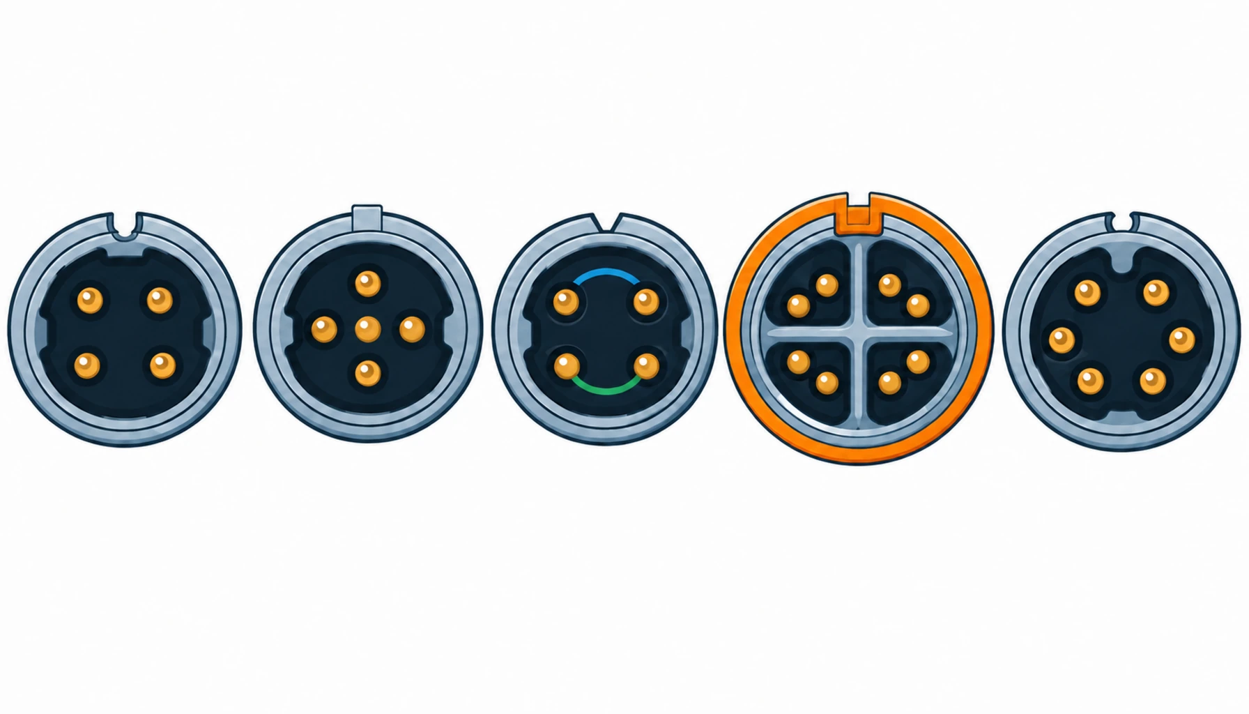
Quick Answer: M8 and M12 circular connectors carry most of the sensor, actuator and network traffic on an automated line, and they are bought by the hundred. The coding letter on a M12 decides what the connector is for, and mixing codes is the cheapest way to stop a line before it starts. What separates a good order from a troublesome one is rarely the brand: it is whether the buyer stated the code, the pin assignment, the shielding requirement and the IP rating that applies once mated, and demanded evidence for each.
Introduction
Walk any modern production line and count the round connectors. Sensors land on M8. Actuator and power signals run through M12 A-coded. Fieldbus and Ethernet ride M12 B, D and X codes. The families are small, standardised and cheap individually, which is exactly why they get bought casually: a part number pulled from the last project, a datasheet nobody reread, an IP figure quoted from the unmated condition.
They also sit at the worst possible place in the reliability stack. An M12 on a moving gantry sees vibration, flex at the cable entry, coolant mist and the occasional blast from a washdown hose. When one fails intermittently, the fault looks like a sensor problem, then a PLC problem, then a software problem, before anyone checks a contact. This guide sets out what the codes mean, which specification lines decide field behaviour, and what evidence to demand in the RFQ. For the cable side of the same assemblies, our special cable range page and the note on industrial Ethernet drag chain cable cover the constructions that land on these connectors.
The Coding System, and What Each Code Commits You To
The code is the keying of the M12: it decides which connectors can mate, and with it the intended application. Buying on price without stating the code is how incompatible connectors arrive on the same line.
A-coded. The general purpose code, 2 to 12 pins, used for sensors, actuators and 24 V power. It is the most common and the most misapplied: an A-coded 4-pin is not a substitute for a D-coded Ethernet connector, because the keying and contact assignment differ.
B-coded. 3 to 5 pins, keyed for fieldbus profiles such as Profibus. Rare on new designs but common in installed bases, and the code keeps it from being mated with anything else.
D-coded. 4 pins, keyed for Fast Ethernet, 100 Mbit/s. The contact layout is optimised for the two pairs Ethernet needs, and the whole path from cable through connector has to be built for it.
X-coded. 8 pins, four pairs, for Gigabit Ethernet. This is the code where shielding and pair symmetry matter most, because the data rate does not forgive a sloppy screen termination or a split pair.
M8 connectors use a smaller shell with simpler coding, mostly 3 and 4 pins for sensors and a 6 or 8 pin range for signals. The selection logic is the same at lower current, and the strain relief window is tighter, which matters more than people expect.
The Decision Table: M8 and M12 Variants and What to Specify on Each
Read the last two columns under time pressure: what each variant costs you in lead time, and where each one fails in service.
| Variant | What to Specify | Evidence to Demand | Cost and Lead-Time Driver | Where It Fails in Service |
|---|---|---|---|---|
| M8, 3-4 pin (sensors) | Pin count, current per contact, cable diameter range of the strain relief, overmolded or field-wireable | Rated current at stated contacts, sealing figure for the mated pair, strain relief clamping range | Overmolded pigtails are stock items; field-wireable bodies are cheaper per unit and cost labour on site | Cable pull-out at the gland, contacts bent by misalignment in tight sensor mounts |
| M12 A-coded (power and signal) | Pin count and assignment, current at the declared contact count, voltage rating, locking torque or snap-in | Derating data at the stated contact count, mating cycle figure, material and contact plating | Standard variants ship fast; unusual pin counts and special plating are factory orders | Contact fretting on vibrating gantries, threads cross-mated between lookalike housings |
| M12 B-coded (fieldbus) | Profile and pinout named, screening concept, termination method at the contact | Screen coverage and termination detail, bus profile conformity statement | Installed-base compatibility drives the order; confirm the profile before switching suppliers | Bus dropouts traced to screen pigtails and to mixed-profile connectors on one segment |
| M12 D-coded (Fast Ethernet) | Category through the whole channel, shield class, pair assignment, IP rating of the mated pair | Channel test report to the declared category with the connector in circuit | Certified data connectors carry a price step; one family across the platform recovers it | Category lost through one non-compliant element, contamination after washdown |
| M12 X-coded (Gigabit Ethernet) | Category 6A path declaration, 360-degree screen termination, pair symmetry, connector and cable as one tested set | Channel test to the declared category, screen termination drawing, return loss data | X-coded assemblies are the most test-sensitive; qualify the cable and connector together, not separately | Gigabit links that negotiate down after temperature cycling, screen defects that pass a continuity check |
Shielding: Where Most M12 Problems Actually Start
The connector is usually not the weak link in a screened circuit; the transition into it is. A screened cable that arrives at the connector and continues as a pigtail wire has thrown away most of the screening the cable paid for, and the symptom appears as noise on an encoder line or as an Ethernet link that renegotiates when the drive next to it speeds up.
The specification should state the screening concept, not just the word “shielded”. Where the circuit is fast or the environment is electrically noisy, require 360-degree screen termination at the connector: the screen clamped over its full circumference at the entry, not gathered into a wire. Our note on servo cable construction explains the cable side of that bargain, and the encoder case is covered in encoder cable. On the connector side, ask the supplier to state the screen termination method per family and to provide the detail drawing; a supplier who cannot draw it is not building it.
X-coded circuits deserve one more line: the cable and the connector should be qualified as one assembly. A category rating is a property of the channel. Where the assembly is bought rather than built, require the channel test report with that connector in circuit, not a component datasheet.
Sealed or Not: Reading IP Claims Correctly
IP67 means the connector survives immersion in the mated condition. It says nothing about the connector sitting open on a bracket during commissioning, and nothing about water pressure from a washdown lance, which is an IP69K duty. Stating where the sealing applies, and assuming a field-wireable connector seals as well as a factory overmold, are the two places buyers go wrong here.
For wet and washdown zones, state the rating you need in the condition that matters: mated for service, unmated with a protective cap where connectors are parked, and high-pressure jet where hoses are used. Our note on IP ratings for robot connectors sets out the boundaries in detail. For the connector itself, ask for sealing evidence in the mated condition and, where the connector can sit open, for the cap that keeps the contacts serviceable between assembly steps.
Overmolded or Field-Wireable
Every M8 and M12 family comes in two build forms, and the choice is a procurement decision before it is a technical one.
Overmolded pigtails arrive factory-built: connector, strain relief and cable moulded as one, tested before shipping. They cost more per unit and fix the cable length in the order, but they remove the on-site crimp variable entirely. For moving axes and washdown zones they are the default choice.
Field-wireable connectors arrive as a body, contacts and gland, and get assembled where the harness is cut. They win on spares logistics, on fitting inside tight cabinets, and on projects where cable lengths are known late. They cost assembly labour, they depend on tooling and workmanship, and their sealing depends on the installer. Where you buy them, buy the termination process with them: our note on terminating robot harnesses covers the crimp quality evidence that should travel with a field termination programme.
Most lines end up with a split: overmolded on the machine, field-wireable in the cabinet and for spares. That split is worth writing down as a platform rule.
What to Freeze Before the Order Goes Out
| Item | What to State | Evidence to Attach | Cost of Leaving It Open |
|---|---|---|---|
| Code and pinout | The code and pin assignment per circuit, aligned with the platform standard | A connector schedule mapping circuits to codes | Incompatible connectors on one line, and a commissioning week lost to adapters |
| Current and voltage | Rating per contact at the declared contact count and duty | Derating data at the stated contact count | Contacts running hot at full load, or connectors oversized and overpriced |
| Build form per zone | Overmolded on moving axes, field-wireable in cabinets, stated as a rule | A platform rule sheet, not case-by-case choices | A spares bin full of one-off assemblies that fit nothing |
| Screening concept | 360-degree termination where the circuit is fast or the plant is noisy | Screen termination detail drawing per family | Noise faults fixed with ferrites instead of the missing clamp |
| IP condition | The rating required in the mated condition, per machine zone | Sealing evidence for the mated pair; caps where connectors park open | Washdown zones that fail inspection, or connectors replaced every quarter |
| Channel category | The Ethernet category through the whole path, connector included | Channel test report with the connector in circuit | A link that negotiates down, blamed on the switch and never fixed |
| Cable diameter match | Strain relief clamping range matched to the actual cable jacket | Cable datasheet against the gland range | Cable pull-out at the gland, the most common M8 failure on record |
| Sample qualification | Samples before volume, acceptance criteria per test | A written qualification plan with pass thresholds | A thousand connectors accepted on one datasheet nobody tested |
When an M12 Specification Is Not the Answer
Where the failure is really the cable entry. A connector replaced three times at the same position is not a connector problem. If the gland clamping range does not match the jacket, or the routing pulls the cable sideways out of the backshell, the replacement fails the same way. Fix the transition before the part. Our note on why robot connectors fail lists the failure signatures worth learning before the third replacement.
Where the environment needs a bigger family. M8 and M12 cover sensor and network duty well, but high-current servo feeds and brake circuits usually belong in M23 or rectangular families. Specifying parallel A-coded connectors to carry a feed they are not rated for is a false economy; the note on M23 connectors for servo and feedback covers where the boundary sits.
Where every connector is treated as a commodity. A connector on a static cabinet wall is a commodity. The same part number on a rotating wrist is not, and a specification that does not distinguish the two duties will buy the same failure twice.
Where price was the only question. The unit price difference between a compliant X-coded assembly and a cheap lookalike is trivial against one week of Gigabit links negotiating down. The datasheet will look the same; the channel test will not.
RFQ Checklist
- Code and pin assignment named per circuit, aligned with the platform standard
- Current and voltage rating per contact, at the declared contact count and duty
- Build form stated per zone: overmolded on moving axes, field-wireable in cabinets
- Screening concept stated, with 360-degree termination where the circuit is fast or noisy
- IP rating declared for the mated condition, per machine zone, with caps where relevant
- Ethernet category declared through the whole channel, connector included
- Channel test report required with the connector in circuit, not a component datasheet
- Strain relief clamping range matched to the actual cable jacket diameter
- Sealing evidence for the mated pair, and mating cycle figure for service planning
- Sample qualification protocol agreed with pass criteria before volume release
Conclusion
M8 and M12 connectors are small, standardised and easy to buy badly. The discipline that keeps them off the fault list is the same as everywhere else in an automation harness: name the code and the pinout, decide the build form per zone, state the sealing and screening requirements in the condition that matters, and demand test evidence from the assembly.
Kexingyu Cable Group (KXYE) supplies the cable side of these assemblies: the continuous flex and drag chain constructions that terminate into M8 and M12 connectors on moving axes and in chains, matched to the clamping ranges of the connector families you have standardised on. Send us the connector schedule and the duty per route, and we will return the constructions and sample lengths that fit; the fastest route is a request for quotation. Where the project needs qualification evidence before volume, our note on robot cable sample testing shows what a good programme covers.


