
Buying Han and HDC Heavy-Duty Rectangular Connectors: What to Specify for Industrial Duty
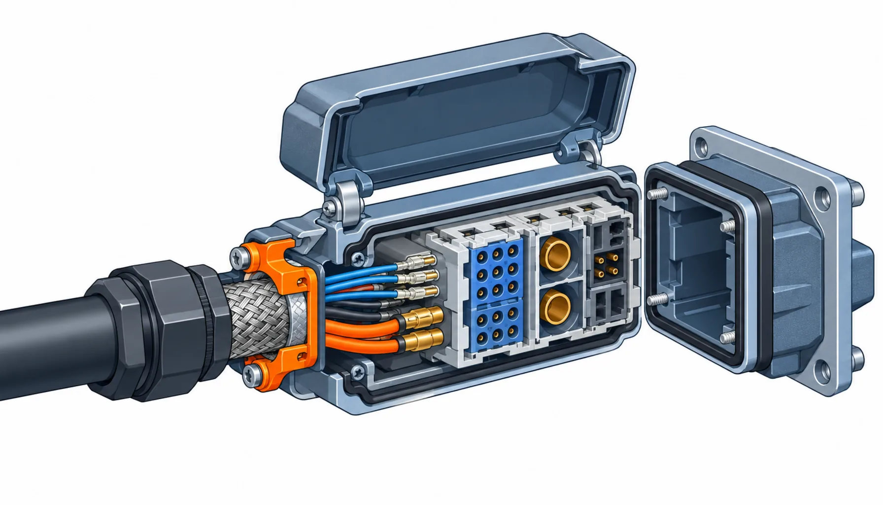
Quick Answer: A heavy-duty rectangular connector is not one product but a modular system: an insert that carries the contacts, a hood that carries the cable entry and sealing, and a housing that carries the mounting. That modularity is why these connectors survive on cranes, wind turbines and rail vehicles, and it is also why they are easy to buy wrong. The order that works states the insert, the hood and the contact termination as three specified items with evidence for each, instead of one family name and a price.
Introduction
Wherever a machine needs its main power or its whole control interface disconnected with a lever, you find the heavy-duty rectangular connector: the Han and HDC families and their equivalents, in hinged hoods with steel locks, carrying tens or hundreds of amps per contact. They sit at cabinet walls, on crane reels, in wind turbine nacelles, under rail car skirts.
The buying problem is different from the circular families. With an M12 the decision is a code; here the decision is an assembly configured from a catalogue of inserts, hoods, contacts and glands, and every choice in the stack affects sealing, current rating and service life. This guide walks the system and lists the evidence an RFQ should demand. For the cable side of these assemblies, our special cable range page shows the families that carry the flex and torsion duty before the connector takes over.
What Heavy-Duty Means, and Where the Standard Draws the Line
The working definition sits in IEC 61984, the standard for connector safety requirements, which rates connectors by voltage, current and the environments they are qualified for rather than by pin count. In practice, this family is defined by three things: contact currents from around 10 A up to 200 A and beyond in single-pole formats, mechanical protection through the hood and gasket system rather than potting, and a locking mechanism designed to be opened thousands of times by a technician with gloves on.
The rating that matters most is the one buyers least often read: the current figure applies per contact at a stated number of adjacent loaded contacts, and it derates as the insert fills up. A 16 A insert is not a 16 A insert when all ten contacts carry full load.
The Modular System: Insert, Hood, Contact
The modular system means every order is really three orders, and mixing assumptions between them is the commonest specification failure.
The insert carries the contacts and decides the electrical character: pin count, current per contact, voltage class, contact assignment. Inserts come as multipole signal formats, power formats, and hybrid formats that combine power, signal and data contacts in one frame. The insert is also where the platform decision lives: two machines sharing an insert standard share spare parts.
The hood and housing decide the mechanical and environmental character: cable gland or side entry, bulkhead mounting for cabinet walls, surface mounting for machines, and the gasket system that decides the IP rating in the mated condition. EMC versions add a shielding concept that clamps the cable screen to the hood over its full circumference. Size series are not cross-compatible, so the hood must be ordered against the insert.
The contacts are bought separately and crimped or screwed onto the conductors. Contact selection follows conductor cross-section first and plating second, and the crimp barrel must match both.
The Decision Table: Insert Families and What to Specify on Each
| Family | What to Specify | Evidence to Demand | Cost and Lead-Time Driver | Where It Fails in Service |
|---|---|---|---|---|
| Multipole signal inserts (10-16 A) | Pin count and assignment drawing, current per contact at the stated loaded-contact count, voltage class, plating | Derating table at the filled insert, mating cycle figure, IEC 61984 conformity statement | Standard pin counts ship from stock; special assignments are configured orders | Contacts running hot when the insert is filled beyond the derating assumption |
| Power inserts (16-35 A) | Contact size against conductor cross-section, phase and PE assignment, PE contact make-first-break-last behaviour | Temperature rise test at full load, PE contact resistance data | Copper contact mass and plating drive price; PE-protective contacts cost more than signal pins | Loose screw terminations backing out under vibration, discoloured PE contacts found at service |
| High-current single-pole (48-200 A) | Contact diameter and plating, conductor luge or crimp format, hood pair rated for the current, touch-proof assignment | Temperature rise at rated current, short-circuit withstand statement, touch protection evidence | Bulk copper and silver plating dominate cost; lead time lengthens with plating thickness | Hot spots at under-torqued terminations, insulation wear where hoods of the wrong frame were paired |
| Hybrid inserts (power + signal + data) | Zone assignment on the insert, screening concept for the data section, segregation distances stated by the maker | EMC evidence for the data section, crosstalk or attenuation data where a category is claimed | Hybrid inserts replace two connectors and one cabinet pass-through; savings show at installation, not on the part price | Data circuits degraded by power-side coupling where the zone assignment was ignored at assembly |
| Hoods, housings and glands | Frame size matched to the insert, IP rating required in the mated condition, entry direction and gland range against the actual cable, locking style | Sealing test for the mated pair, gland clamping range, EMC hood screen termination detail where shielded | Standard hoods are stock; EMC and high-IP variants are configured items with longer lead time | Gasket compression set after heat cycling, glands mismatched to cable jacket causing pull-out |
Contacts and Termination: Crimp, Screw or Spring
The termination method is the part of the connector most exposed to workmanship, and it should be named per contact class rather than left to the assembler. Crimp contacts give the best vibration performance and are the default on moving machinery; they demand controlled tooling and pull-off force evidence from the batch, the same discipline our note on terminating robot harnesses applies to the smaller families. Screw terminations are serviceable and forgiving in cabinets but rely on torque discipline, which is why they back out on vibrating structures.
Plating deserves its own line in the specification. Tin plating is standard and adequate for low mating counts; silver carries higher currents and survives temperature; gold-flashed contacts appear on signal and data sections where stable contact resistance matters. Our note on connector contact plating sets out the trade-offs, and the specification should name the plating rather than accept “standard”.
Sealing and EMC in the Mated Condition
Two conditions decide whether the environmental specification means anything, and both get skipped in casual orders.
The first is the mated condition itself. The IP figure on the datasheet applies to the connector closed and locked, with the gland matched to the actual cable diameter and the gasket seated on a clean flange. Open the hood for service and the rating no longer applies; state which locations need caps or dummy plugs for the open state.
The second is EMC. A shielded cable that enters an unshielded hood has lost its screen at the last metre. EMC hood versions clamp the screen over its full circumference at the entry; the specification should require the screen termination detail drawing, and our note on shielded connectors and EMC explains what a complete screen path looks like. The transition from cable to hood is likewise a mechanical duty, and our note on the strain relief and connector interface covers the clamping geometry that keeps the termination from carrying the flex.
Wind, Rail and Port Duty
Three sectors buy a disproportionate share of the value in this connector class, and they buy against specifications that go beyond the standard catalogue line.
Wind turbines. Nacelle and converter interfaces combine vibration, wide temperature swings and service intervals measured in years between climbs. Connectors qualified for the duty carry type approval evidence against the relevant wind standards, and the cable feeding them is part of the same qualification; our wind power special cable page shows the torsion and cold-flex constructions that land on these connectors.
Rail vehicles. Under-floor and roof interfaces work to fire behaviour and vibration requirements from the rail standards, with EN 45545 the usual reference for material fire performance. Connectors here are bought with material certificates and a documented vibration profile, and lead times reflect that paperwork; plan orders around it.
Ports and cranes. Reel drums, festoons and slew ring pass-throughs put continuous flex and torsion duty on the cable side and shock loads on the hood side. The connector is only as good as the cable entry, and our notes on port automation cable and on crane and cable reel cable cover the constructions that keep the entry from becoming the failure point.
What to Freeze Before the Order Goes Out
| Item | What to State | Evidence to Attach | Cost of Leaving It Open |
|---|---|---|---|
| Insert schedule | Pin count, assignment and current per contact, per connector on the machine | An insert schedule with assignment drawings | Configured inserts re-ordered at premium, and a machine that cannot be serviced with its own spares |
| Derating basis | Current figures at the stated number of loaded contacts, not the headline rating | Derating table for the filled insert | Contacts running hot two years in, traced to an assumption nobody wrote down |
| Termination method | Crimp on moving machinery, named tooling and process standard | Batch pull-off force records from the shipped lot | Intermittent terminations that surface as control faults on the third shift |
| Plating per contact class | Tin, silver or gold named per duty, not "standard" | Plating specification and thickness declaration | Contact resistance drift on signal circuits, and plating swaps at premium prices later |
| IP condition | Rating required in the mated condition, per location, plus caps for open states | Sealing test for the mated pair and gland range against the actual cable | Washdown and outdoor locations serviced quarterly instead of yearly |
| EMC concept | EMC hoods with 360-degree screen clamping where screened cable is used | Screen termination detail drawing per hood type | Noise faults fixed with ferrites and guesswork instead of the missing clamp |
| Frame compatibility | Hood, insert and contacts ordered as one matched set per connector | A bill of materials per connector, not per element | Mismatched frames discovered at installation, with the line waiting |
| Sector approvals | Rail fire materials, wind type approval or port duty evidence named where they apply | Certificates and test reports against the named standards | An order that passes the factory and fails the site inspector |
When a Heavy-Duty Rectangular Connector Is Not the Answer
Where the circuit is a servo or feedback loop on a moving axis. Rectangular connectors excel at cabinet interfaces and main feeds, but a rotating joint or a dress pack route usually belongs in the circular families, where the sealing and strain relief are built around continuous flex. Our note on M23 connectors for servo and feedback marks the boundary.
Where the cable count is the real problem. If the driver for a giant insert is twelve separate cables, a hybrid insert or a composite cable removes cables rather than enlarging the connector; our note on hybrid power and signal connectors covers that route.
Where the connector is being blamed for a cable entry failure. A hood replaced twice at the same position is a symptom. Check the gland range against the actual jacket, the bend radius at the entry and the clamping geometry before the third replacement; our note on why robot connectors fail lists the signatures worth learning.
Where the duty is occasional and indoor. A latched rectangular connector with EMC hood and IP67 gaskets on a static, dry, indoor cabinet is overspecification. The cheaper screw-terminal format does the same job for decades, and the price difference funds specification discipline where it actually earns.
RFQ Checklist
- Insert schedule with pin count, assignment drawing and current per contact at the stated loaded-contact count
- Derating table for each filled insert, not the headline current figure
- Termination method named per contact class, with tooling and process standard
- Batch pull-off force records from the shipped lot for crimped contacts
- Plating named per contact class, with thickness declaration
- IP rating for the mated condition per location, with caps or dummy plugs for open states
- EMC hoods with 360-degree screen termination where screened circuits are present, plus the detail drawing
- Hood, insert and contacts ordered as one matched bill of materials per connector
- Gland clamping range confirmed against the actual cable jacket diameter
- Sector certificates named where applicable: rail fire materials, wind type approval, port duty evidence
Conclusion
Heavy-duty rectangular connectors reward buyers who treat the order as a system. Name the insert with its assignment drawing and derating basis, the hood with its sealing and EMC evidence, and the contacts with their termination process, and the connector disappears from the fault list. Leave any one of the three to chance and it becomes the failure that arrives two years in, wearing the machine’s name.
Kexingyu Cable Group (KXYE) supplies the cable side of these assemblies: the flex, torsion and cold-rated constructions that feed heavy-duty connectors on cranes, reels, nacelles and machine frames, matched to the gland ranges and screen clamping of the hood families you standardise on. Send us the connector schedule and the duty per route, and we will return the constructions and sample lengths that fit; the fastest route is a request for quotation.


