
Robot Joint Cable Routing: What to Specify for Bend, Twist and Service Loops
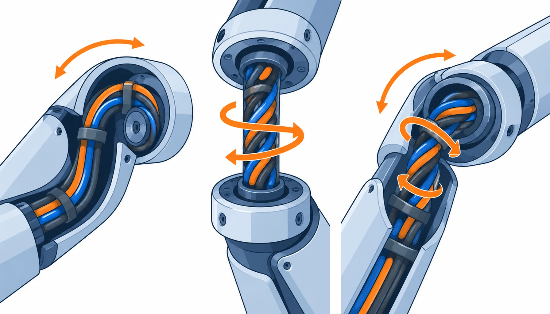
Quick Answer: A joint cable rarely dies because the cable was the wrong grade. It dies because of how it was routed. Bend radius, torsion angle, loop length and clamp position decide what the cable experiences, and left to the assembler those four numbers get decided by whatever fit at the time. The fix is cheap: put the routing on a drawing, name the bend radius and torsion rate, give the service loop a length and a tolerance, and require evidence at those values.
Introduction
Every axis on a robot asks the cable for something different. A shoulder or elbow sweeps through a bend. A wrist rotates and puts the bundle into torsion. A tool axis may do both at once. The cable you buy and the way you route it are two halves of one decision, and buying well while routing badly is the most common way a joint cable fails early.
The harness overview in our note on robot harnesses and connectors places the cable among the other elements. This guide stays on the routing itself: what the joint does to a cable, which path to choose, how to size a service loop, and what to write into the order.
What a Joint Actually Does to a Cable
A robot joint produces three kinds of motion, and each damages a cable differently. Bending stretches the outer layers of the bundle and compresses the inner ones, working the jacket, the screen and the conductor strands at once. Torsion rotates the layers against each other, since each is laid at its own pitch, and a long twist opens the screen and lets the cores migrate. Combined motion is worst of the three, because the cable is bent while it is twisted and the two stresses add at the same point.
The point for a buyer is that the cable does not see the joint angle. It sees the bend radius and the torsion rate the routing gives it. A joint that sweeps 180 degrees can be routed as a generous loop or as a tight fold, and the difference in life is set by a routing drawing.
The Three Motions and What Each Demands
A static run only has to reach, so length and clamping are the whole specification. A bend-only axis is governed by the minimum bend radius and the bending cycle count, which is why a continuous flex construction is bought by cycle count rather than by a general flex claim. A torsion axis is governed by the angle turned per unit of length, and a layered build with short lay lengths handles that far better than a standard cable. Where both happen at once, the routing should keep them in separate parts of the run, so the bend section is not also the twist section.
For the bend case, our notes on minimum bend radius and on continuous flex versus drag chain cable set out how the radius and the cycle count interact. For the twist case, torsion rated cable construction covers what changes inside the cable when the axis rotates rather than bends.
The Decision Table: Routing Paths and What Each One Costs
| Routing Approach | Cable to Buy | What to Specify | Evidence to Demand | Where It Fails in Service |
|---|---|---|---|---|
| Static run inside a link | Standard flex construction | Length tolerance, clamp positions and the clearance to the bore wall | A routing drawing with clamp points marked | Chafing at the clamp edge where the jacket is held hard |
| Bend-only service loop | Continuous flex, rated by cycle count | Minimum bend radius, bending cycles and the loop diameter | A flex test run at the specified radius and cycle count | A loop that is too tight, or one that migrates until it is |
| Twist axis through the joint | Torsion rated, layered construction | Torsion angle per metre and the number of twist cycles | A torsion test at the specified angle and cycle count | Screen opening and core migration after a few hundred thousand cycles |
| Hollow shaft or through-arm route | Small diameter, low friction jacket | Outside diameter clearance, bore radius at the entry and slip fit | A fit sample passed through the actual bore | Abrasion against the bore edge, then a screen fault |
| External dress pack | Abrasion resistant, UV stable jacket | Support spacing, loop shape and the entry transition at each end | An abrasion test plus the sag and clearance drawing | Sag that snags on the fixture, and wear where it rubs |
Service Loops: Length, Position and Why Millimeters Matter
A service loop is not spare cable. It has three jobs: absorb the length tolerance of the assembly, give a technician something to work with during a service swap, and keep the point where the cable is clamped away from the point where it has to move. A loop that does none of those is just slack.
Length is where most of the trouble hides. Too short, and the loop pulls straight at the end of travel, putting the bundle in tension and loading the connector. Too long, and it swings with the axis, rubs against the link and catches on the fixture. The useful range is narrow, set by the axis travel, the loop diameter that keeps the bend radius above the cable’s limit, and the clearance around the joint.
Position matters as much as length. A loop should sit in one plane. If it has to bridge two axes, the cable is bent in one direction and twisted in another at the same time, which is the combined motion that wears a bundle fastest. Clamping the bundle on both sides of the loop, with the loop free to move in between, gives the cable a defined place to bend instead of letting it find its own. Where a loop ends at a connector, the transition belongs to a strain relief rather than to the loop itself, and the entry mechanics are set out in our note on strain relief at the connector interface.
Millimeters matter because the loop shape is set by the distance between two fixed points. With a loose length tolerance and drifting clamp positions, a loop designed as a generous arc can be built as a tight fold on one unit and a slack tangle on the next, from the same drawing. A tolerance on the loop length and a position on the clamp are what make the drawing reproducible on the line.
What to Freeze Before the Order
| Item | What to State | Evidence to Attach | Cost of Leaving It Open |
|---|---|---|---|
| Minimum bend radius | The radius the routing actually imposes, not the catalogue minimum | A routing drawing with the loop diameter dimensioned | A loop drawn tighter than the cable can take, failing in months |
| Torsion rate | The angle turned per metre of bundle, with the cycle count | A torsion test at that angle and length | Buying a flex cable for a twist axis and losing the screen |
| Cycle count | The bending or twisting cycles over the service life, stated per axis | A flex or torsion test run to that count | A cable rated for a duty it never sees, or one that is over-specified |
| Clamp positions | Where the bundle is fixed, on both sides of every loop | A drawing showing each clamp and its hardware | A bundle that migrates until it rubs on a link edge |
| Service loop length | The loop length and its tolerance, plus the diameter it must keep | A first-article measurement on the built harness | The same drawing building tight loops on some units and slack on others |
| Entry strain relief | The relief method at every connector, with the bend start point | A drawing showing the bend starting clear of the shell | Bending concentrated at the connector, cracking the seal |
| Jacket and friction | Jacket material and its friction against the bore or guide it runs in | A sample dragged through the actual guide or bore | Wear that opens the screen before the conductors fail |
| Routing drawing | One drawing per axis, issued with the order and kept current | The drawing revision tied to the part number | Field routing decided at build, invisible in every warranty claim |
When a Service Loop Is Not the Answer
Where the joint rotates continuously. A loop cannot survive a full turn, let alone thousands, because it will wind up and break. If an axis rotates without a hard stop, the answer is a slip ring or a rotary union rather than a longer loop.
Where there is no room for the correct radius. If the link geometry cannot fit the bend radius the cable needs, the answer is a different route or a different construction, not a softer jacket folded tighter. A soft jacket folds more easily and fails sooner, because jacket flexibility has nothing to do with the strain limit of the conductors inside it.
Where the torsion is beyond the construction. If the axis turns further per metre than the cable is built for, no amount of looping fixes it. The options are a torsion rated build with a shorter lay length, a reroute that spreads the twist over a longer section, or a change to the motion itself. Routing cannot rescue a cable asked to twist past what its build allows.
Where the order has no routing drawing. Routing left to the build floor gets decided by whoever is assembling that unit, and it will not be the same twice. Where the harness leaves the robot is covered in our note on dress pack cable, and the choice between routing inside the arm and running outside it is the subject of our note on internal wiring versus a dress pack.
RFQ Checklist
- Bend radius stated as the value the routing imposes, with the loop diameter dimensioned on a drawing
- Torsion angle per metre and twist cycle count named for every rotating axis
- Bending and twisting cycle counts stated per axis, not as one figure for the machine
- Clamp positions shown on both sides of every service loop, with the hardware called out
- Service loop length and tolerance stated, with a first-article measurement required
- Strain relief named at every connector entry, with the bend starting clear of the shell
- Jacket material and its friction against the bore or guide it passes through
- One routing drawing per axis, tied to the part number and issued with the order
- Flex and torsion evidence requested at the specified radius, angle and cycle count
- Continuous rotation axes identified at enquiry, so a slip ring can be priced instead of a loop
Conclusion
Joint cable routing is the cheapest reliability decision on the machine and the one most often left to the build floor. The bend radius, the torsion rate, the loop length and the clamp positions decide what the cable experiences, and each can be written down in a sentence on a drawing. Buy the construction that suits the motion, put the numbers in the order, and ask for flex and torsion evidence at your values rather than at the supplier’s favourite test setting.
Kexingyu Cable Group (KXYE) supplies the cable side of robot joint routing: continuous flex and torsion rated constructions, including the robot composite cable built for moving axes, with stranding and lay lengths chosen for the bend and twist the routing imposes. Send us the axis motion, the routing sketch and the cycle counts, and we will return constructions and sample lengths that fit; the fastest route is a request for quotation.


