Field Ampacity Derating: Turning Site Conditions into a Cable Size
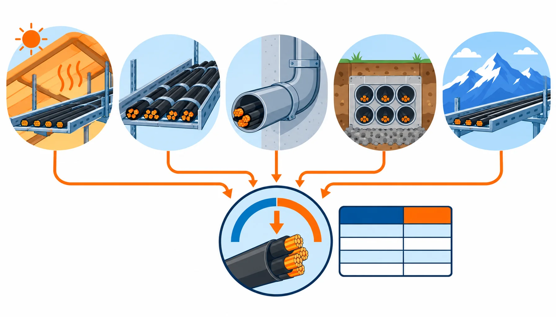
Quick Answer: Cable ampacity derating is the process of turning a catalogue figure measured under reference conditions into the current a cable can actually carry where it is installed. Ambient temperature, grouping, installation method, soil and altitude each reduce the figure, and they multiply rather than add. The buying job is to get the derated current calculated in the right order, on the real site conditions, and then choose the cross-section against that number rather than the table.
Introduction
The table in a catalogue is measured under a defined set of conditions: a stated ambient, a defined installation method, a single circuit and a defined soil. A real route almost never matches all of them at once, and the difference is what the derating calculation exists to close.
This guide is written for the buyer who has to fix a cross-section before the enquiry goes out. It sets out the factors that matter on site, the order to apply them, how the result lands in the specification, and what to freeze in the order. The general treatment of the factors themselves sits in our note on cable derating factors; this article is about using them to size a purchase.
Why Field Ampacity Differs From the Table
Reference conditions are a fiction you agree to share. The published figure assumes the cable sits in an air temperature that is rarely the temperature at a hot roof void, and that it runs alone when it usually shares a tray. Both assumptions push the real capability down.
The cable fails by heat, not by current. A conductor’s limit is the temperature its insulation tolerates continuously, and the current is only a means to that temperature. Anything that slows the heat leaving the cable, or raises the temperature around it, reduces the current that reaches the same limit.
The corrections multiply. A derated figure for high ambient and a further figure for grouping do not add to a single penalty; they compound, and a route that is hot and grouped can end up needing a cross-section one or two sizes larger than the table suggests.
The cost of getting it wrong runs both ways. Undersize the cable and the circuit trips on a hot afternoon, with the reinforcement cost landing after the trays are full. Oversize it and the buyer pays for copper that carries current nobody uses, on every metre of the order.
A percentage point of ambient or a change in grouping rarely looks dramatic on its own. Stacked across a long route, through several thermal barriers, they are the reason the installed ampacity is often fifteen to thirty per cent below the catalogue figure that started the design.
The Derating Factors That Matter on Site
The table sets out each factor, where it bites, what to state in the specification and how a route fails when the factor was left out of the calculation.
| Factor | Where it bites | What to Specify | Evidence to Demand | Cost and Lead-Time Driver | How It Fails |
|---|---|---|---|---|---|
| Ambient temperature | Roof voids, boiler areas, plant rooms, unventilated shafts | The measured ambient at the cable and the correction applied to the reference figure | A derating calculation naming the ambient used and the margin | Higher-class insulation or a larger cross-section across the whole run | Overload trips at the hottest hour and premature ageing on the hot section |
| Grouping and bundling | Densely loaded trays, ducts and cleated banks of circuits | The number of circuits sharing the support and whether they are all loaded | A group correction factor with the count and the installation method stated | Larger cross-sections, or a wider tray and a new support design | A tray that was sized when it was half full and derates as circuits are added |
| Installation method | Free air, tray, buried, in conduit, in thermal insulation | The method per route section, and the reference method the rating was taken from | Ratings quoted against a named reference method, not a single number | Method changes can move the size more than any single temperature correction | A rating quoted for free air used for a cable that spends its life in conduit |
| Soil and burial | Buried runs, backfilled trenches, duct banks, dry or wet soil | Soil thermal resistivity, burial depth, spacing and duct configuration | Soil resistivity data for the route, or a stated design assumption | Deeper or wider spacing, or a larger cross-section where soil is poor | A shallow run in dry soil that cannot shed heat and heats the whole duct bank |
| Altitude and enclosure | High-altitude sites, sealed enclosures, cabinets and small chambers | The altitude and the enclosure conditions where the cable ends | A correction applied for altitude and for the enclosure, not just the open air | Altitude corrections and enclosure design are cheap at design stage | A cable sized for the open air that sits in a sealed box at the hot end |
Doing the Calculation in the Right Order
Start from the load, not the cable. The design current and the protective device set the target, and the derated cable rating has to sit above it with margin. Working from a cable size outwards to find a load that fits is how undersized circuits get built.
Pick the right reference figure. Ratings are quoted against a named installation method, and using a free-air figure for a ducted route is the single most common error. Ask which method each quoted number rests on, and demand the figure for the method the route actually uses.
Apply the corrections in a consistent order. The reference ambient, the ground or air temperature, the grouping and the method are all applied to the same base figure, and the order has to be the one the standard uses so the result means something. Mixing figures from different bases is how a calculation looks complete and is quietly wrong.
Then check the voltage drop. A cross-section driven up by derating also reduces voltage drop, so the derated size often satisfies both limits. Where the run is long, the drop check can push the size higher still, and it belongs in the same pass.
Then check the fault and the earth. The protective conductor and the fault-temperature limit travel with the chosen size and the protection setting. A derated cable that trips correctly still has to survive the fault current for the clearing time, which is what the insulation resistance and testing regime is there to confirm after installation.
What to Freeze Before the Order Goes Out
Six items turn the calculation into a purchase order. Each one is cheap to state now and expensive to discover at commissioning.
| Decision | What to State | Evidence to Attach | Cost of Leaving It Open |
|---|---|---|---|
| Ambient at the cable | The measured or calculated ambient on each route section, with its basis | A derating sheet showing the ambient used | A cable that derates below the load on the hottest run |
| Grouping count | The number of loaded circuits sharing each support, now and planned | A group factor with the count and method named | Reinforcement after the tray fills, with no room to expand |
| Installation method | The method per section, and the reference method the rating is taken from | Ratings quoted against the named method | A free-air rating used on a ducted route, discovered as an overheating fault |
| Soil and burial data | Soil thermal resistivity, depth, spacing and duct configuration | Soil data or a stated design assumption | A duct bank that cannot shed heat, derating every circuit in it |
| Derated current and size | The derated current per circuit and the cross-section chosen against it | The full calculation, signed against the standard used | A size chosen on the catalogue figure and revisited after the trays are full |
| Conductor and class | Copper or aluminium, the conductor class and the rated voltage | Conductor construction and resistance data | A lighter conductor that costs more in derating than it saved in metal |
Conductor and Insulation Choices That Move the Number
Copper or aluminium is a derating decision as well as a price decision. Aluminium carries less current for the same cross-section and needs a larger size for the same duty, so the weight and the space it saves can disappear in the derated comparison. Our note on aluminium versus copper cable sets out where each one wins.
Insulation class raises the ceiling. Going from a standard PVC class to a 90 C class raises the temperature the conductor may reach, and that raises the derated figure without changing the cross-section. On a hot or grouped route the class can be the cheaper lever, which is the trade covered in our note on the conductor and copper grade behind the price.
The conductor class affects flexibility, not ampacity, but it changes the installation. A finer class is easier to pull through a crowded tray, so the route and the derating interact. Our note on the IEC 60228 conductor classes sets out what each class is for.
Dense trays are the hard case. A high-density route loaded with many circuits derates hardest, and the answer is often a wider tray and more spacing rather than more copper. Our note on the cable tray in a high-density hall shows how that trade is made when the space is fixed.
Altitude, Enclosures and the Places Tables Forget
Two conditions get left out of the calculation more often than any others. The first is altitude, where thinner air removes heat less effectively and a correction applies that a sea-level table does not carry; our note on high-altitude derating covers how that correction is applied. The second is the enclosure at the end of the run, where a cable that was rated in open air finishes inside a sealed box and is loaded on the assumption that it can still shed heat.
Both are cheap to fix at design stage and expensive afterwards, because neither shows up until the circuit is loaded and the temperature is measured. Where a route ends in a cabinet or a chamber, state the enclosure conditions alongside the route conditions and let the calculation see them.
Incoming Inspection and What to Record
Against the schedule. Check the cross-section, conductor class and insulation class delivered against the sizes the calculation produced, per drum, before the cable is cut.
Conductor and resistance checks. Measure conductor resistance on the finished lengths against the declared value, because resistance is where a conductor that is short of copper shows up before it shows up as heat.
Confirm the size actually installed. Where a route is pulled in stages, confirm that the derated size was used on the sections that carry the worst conditions rather than the standard size throughout.
Record the installation conditions. Note the ambient, the grouping and the enclosure at commissioning with the first set of thermal or current readings. Those figures become the baseline that decides whether a later hot spot is a loading question or a cable question, which is the difference between a measured decision and a guess.
When a Bigger Cable Is Not the Answer
When the heat is coming from outside. Where a run is hot because of a nearby process line or a radiant source, a metallic barrier or a change of route removes the heat far more cheaply than adding copper to every circuit.
When the tray is simply too full. Adding cross-section to every circuit because one support is overloaded wastes copper on the whole route. A wider tray or a second support often costs less than the metal the derating would otherwise demand.
When the load is not what the design assumed. Oversizing because the design used a pessimistic ambient and a pessimistic grouping compounds two margins into one and pays for both. The calculation should use the conditions that will exist, not the worst case no route ever sees.
When the class is the cheaper lever. A higher insulation class raises the ceiling without touching the cross-section, and on a hot route it can remove the size increase entirely. Match the lever to the factor that is actually binding.
RFQ Checklist
- Design current, protective device and the factor of safety applied
- Reference installation method for each route section, and its basis
- Measured ambient at the cable on each section, not the site average
- Grouping count per support, and whether the other circuits are fully loaded
- Soil thermal resistivity, depth, spacing and duct layout for buried runs
- Altitude and enclosure conditions where they apply
- The derated current per circuit and the cross-section chosen against it
- Conductor material, class and rated voltage, with resistance data
- Voltage drop and fault-current check for the chosen size
- Conductor resistance and insulation resistance tests to be supplied per drum
Conclusion
Field ampacity is the number that decides the cable, and it is built by applying site conditions to the catalogue figure in a consistent order. Get the ambient, the grouping, the method and the soil into the calculation, use the reference method the route actually follows, and choose the cross-section against the derated current rather than the table. The cable that trips on a hot afternoon and the cable that was oversized for a worst case nobody ever sees are both bought with the same mistake: sizing on a figure that was never true for the route.
Kexingyu Cable Group (KXYE) has manufactured cable in Quanzhou since 1996, supplying copper and aluminium constructions across IEC and GB conductor classes for grouped, high-ambient and buried duty, with resistance and construction data that travels with the drums. Send us the route schedule with the loads, the ambients and the installation methods, and we will come back with the cross-sections, the derating basis and a delivery plan against your programme. A request for quotation is the fastest route.