
Buying DCIM Power Monitoring for Cable Capacity: What to Specify and What to Verify
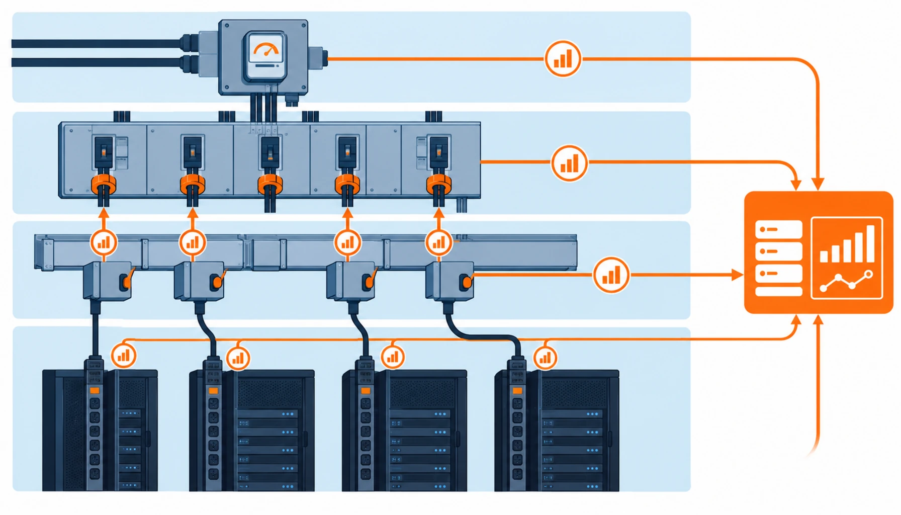
Quick Answer: Cable capacity is stranded capacity. It exists in the copper, but nobody knows it is there, so the next rack is fed from a new circuit instead of from the spare capacity already installed. A DCIM power monitoring platform is bought to make that visible. The purchase has three parts that must be specified together: the metering points and their accuracy class, the asset register that ties every reading back to a cable reference, and the alarm thresholds that turn a reading into an action. Buy the software without the first and third and you own a graphing tool. Specify all three and you can defer cable work by years.
Cable is one of the few assets in a data hall that cannot be upgraded without disrupting what is running. Once a submain is installed, the ceiling for that route is fixed until the next shutdown window, so using it well is a monitoring problem rather than an engineering one.
Introduction
Most DCIM projects are bought as software and judged as software. The tender asks for dashboards, integrations and reporting, and the responses are compared on features. Six months after go live, the operations team is still walking the hall with a clamp meter to answer the one question the platform cannot: how much of this cable is actually in use.
The reason is structural. Monitoring systems do not measure cable. They measure current where a current transformer can be fitted, and infer the rest from a database that has to be loaded with the cable schedule. Where that mapping is incomplete, the platform reports on circuits nobody can identify and stays silent on the routes that matter. Our notes on intelligent PDU metering and on cable labeling and documentation at handover cover the two halves of that problem.
Why Cable Capacity Is the Hard Part
Rack power is easy to monitor because a rack has one or two feeds and a name. Cable capacity is hard because a single cable serves many racks and its limit is thermal.
A 630 A submain at 63% of rated current in a 35 °C ambient is not at 63% of its thermal limit. Derating for grouping, tray fill and ambient can bring the usable limit to 70% or less of the nameplate figure, and the remaining margin exists only if the derating assumptions were recorded. Without them the platform has no basis for an alarm and will report normal conditions until an insulation fault appears. Three factors widen the gap on new-build halls.
Design margin is spent before go live. A route designed with 30% spare capacity and delivered with three extra circuits tapped by the fit-out contractor is at its limit on day one, and without measured load that is invisible.
The nameplate is not the limit. Published cable ratings assume defined installation conditions. Real installations depart from them, and the difference is where most stranded capacity hides.
Diversity assumptions drift. A hall designed on 0.8 diversity and operated at 0.95 has a real problem that no capacity plan will show. The demand side of that trend is set out in our note on data center power demand growth.
Four Measurement Layers and What Each One Can Answer
Power monitoring in a data hall is built from four layers, and a platform’s usefulness is decided by how many of them are instrumented. Buying the top layer without the two below it is the most common specification error in this category.
Utility and main intake. Incomer meters give total site load and power factor and are almost always present because the utility requires them. They cannot tell you which route is loaded.
Distribution board and submain. Branch circuit monitoring is where cable capacity becomes visible, because it is the first layer at which a reading maps to a specific cable. Buy it first; it is also the layer most often cut to hit a budget.
Busway and tap-off. Metered tap-off boxes turn a passive busway run into a measured one. Retrofitting metering later costs several times the factory option, so the requirement belongs in the busway order rather than the DCIM order.
Rack and PDU. Rack PDUs close the loop at the point of use, but they only reconcile to cable capacity if the board level layer exists above them.
The Decision Table: Monitoring Architectures Compared
The table compares the four architectures a buyer will be quoted, priced against what each one can actually answer.
| Architecture | What to Specify | Evidence You Should Receive | Cost and Lead Time Shape | Failure Mode If Chosen Wrong |
|---|---|---|---|---|
| Software only | Protocols supported, tag naming convention, asset import format, alarm rule engine, retention period | Licence schedule, integration test report against a live feed, sample dashboard using project tags | Lowest capital cost, fastest to order; delivers nothing without instrumentation | A dashboard that graphs the intake meter and no cable; stranded capacity stays invisible |
| Board and submain metering | Metering per outgoing circuit, accuracy class, CT ratio and burden, communications bus, breaker interlock for CT replacement | Factory test certificates per meter, CT ratio records, point list mapped to the cable schedule, FAT with simulated loads | Moderate cost; adds weeks to switchboard manufacture and must be ordered with the board | Retrofit metering required later at several times the cost, with an outage to install CTs |
| Busway with metered tap-offs | Metering in each tap-off, measurement point in the tap-off or the plug-in box, busway temperature sensing where offered | Tap-off meter certificates, address map per tap-off, temperature sensor calibration records | Highest equipment cost, no site labour; specify before the busway order is placed | Un-metered runs that cannot be instrumented later without de-energising the row |
| Full stack with rack PDUs | Rack PDU metering level, outlet or inlet, accuracy, daisy chain limits, firmware and security policy | Per outlet accuracy certificate, poll rate under full count, log reconciling rack totals to board totals | Cost scales with rack count; reconciliation is where projects under-scope labour | Two sets of numbers that never agree, and an operations team that trusts neither |
Specifying Points, Thresholds and Alarms
The specification has to name three things for each monitored circuit: the point, the threshold and the action.
The point. State the measurement location and what it observes, not the equipment type. Board level current, busway tap-off current, cable surface temperature and neutral current on circuits with significant harmonic content are four different points with four different values.
The threshold. Thresholds derived from the derated cable rating rather than the nameplate rating are the ones that protect the asset. For a submain installed in a group on a tray at 35 °C, that may mean an 80% alarm against the derated figure, which can be below 60% of the nameplate number. Our note on cable derating factors sets out how to derive the figure the threshold should be built on.
The action. Every threshold needs an owner and a response: a warning at a workable margin routes to capacity planning, and a trip-level alarm routes to the shift engineer, out of hours if necessary. Where the response is not defined, the alarm becomes background noise within a month.
Two configuration decisions save more effort than any dashboard feature: naming tags to the cable reference used on the as-built schedule, so a reading and a drawing point at the same object, and storing the derating assumptions in the platform so thresholds revise when conditions change.
What to Freeze Before the Purchase Order
| Item | What to State | Evidence to Attach | Cost of Leaving It Open |
|---|---|---|---|
| Tag naming | The convention tying every monitored point to a cable reference in the as-built schedule | Sample export of twenty points in the agreed format | Months of manual rework at commissioning, and a register that drifts from the drawings |
| Metering scope | Which circuits are metered, at which layer, and what happens to unmetered circuits | Point list annexed to the switchboard and busway orders | Retrofit metering after energisation, with an outage and a premium price |
| Accuracy class | The class required for billing grade and the (lower) class accepted for capacity monitoring | Factory certificates stating class and test conditions | Paying billing grade on every circuit, or buying accuracy too low to alarm reliably |
| Threshold basis | The derated rating each alarm uses, and who owns the derating calculation | Derating calculation and the assumptions it rests on | Alarms set against nameplate ratings that never fire before damage is likely |
| Alarm ownership | Who receives each class of alarm, in and out of hours, and the response time | Escalation matrix agreed with the operations team | Alarms nobody acts on, and a real event treated as noise |
| Data retention and export | Raw sample retention, interval retention, and the export format required for audit | Retention policy and a sample archive export | No trend history when a failure investigation needs one |
| Integration and security | Protocols, polling intervals, network segment, firmware update policy, credential handling | Integration test report and a security annex | A building management system that cannot see the data, or a device the IT team will not connect |
| Acceptance test | The reconciliation the vendor must demonstrate before final payment | Signed reconciliation of rack totals, board totals and the intake meter | A platform accepted on feature demonstrations and never proven accurate |
When a DCIM Platform Is Not the Answer
Monitoring has a real cost, and on some sites the return is not there.
Small halls with a single tenancy. Where one tenant occupies the whole hall and loads are stable, a quarterly thermal survey and a current log give most of the benefit at a fraction of the cost. Our note on infrared thermography at commissioning sets out what such a survey covers.
Where the asset register is not trustworthy. A monitoring platform multiplies whatever it is attached to. Attach it to a register that no longer matches the installation and it produces confident numbers about cables that have been removed. Fix the register first.
Where the intent is to avoid cable work rather than plan it. Monitoring buys time to plan reinforcement properly. Where there is no plan, a dashboard simply documents the approach to the limit, and our note on planned cable replacement covers how to schedule the work itself around uptime tiers.
Where metering is bought late as an add-on. Metering specified after the switchboard and busway are in manufacture is a variation at a premium. Ask for the metering point list at tender stage and the cost is usually modest.
RFQ Checklist
- Metering point list at each layer, referenced to the cable schedule, annexed to the tender
- Accuracy class stated separately for billing circuits and capacity monitoring circuits
- Current transformer ratio, class and burden required, with space and interlocking for safe CT replacement
- Metering included in the switchboard and busway orders rather than bought separately later
- Busway tap-off metering and busway temperature sensing specified before the busway order is placed
- Tag naming convention fixed and demonstrated on a sample export before contract
- Derated current rating for each alarm, with the derating calculation attached
- Alarm classes, thresholds, recipients and response times, including out of hours
- Escalation matrix signed by the operations team, not only by the project team
- Polling interval under worst case device count, with the vendor’s figure in writing
- Raw and interval data retention periods, plus export format for audit
- Reconciliation of rack totals, board totals and intake meter as a condition of final acceptance
Conclusion
Cable capacity is not created by monitoring it, but it is discovered by it. Capacity a specification has already bought, and a fit-out has already installed, is usually worth more than the next reinforcement project, and worth nothing while unmeasured. The three parts of the purchase, the points, the register and the thresholds, are cheap when specified with the switchboard and expensive when retrofitted around a live hall.
Kexingyu Cable Group (KXYE) supplies the cable and distribution equipment that a monitoring system is ultimately measuring, including the WDZ-YJY, WDZN-YJY, BTTZ, NG-A (BTLY), KVV and YJV ranges, the data center cable range used on submain and riser routes, and the GGD power distribution cabinet and busbar tap-off box where branch circuit metering is best installed, from one factory group with copper price linkage on project-scale orders. Send the point list you intend to meter and the derating basis you intend to alarm on, and we will return the ratings and factory records that support them; the fastest route is a request for quotation.


