Cable Sheath Faults and Ground Faults: Locating and Proving the Damage
Quick Answer: A cable sheath fault is a hole in the outer layer, and a ground fault is what that hole becomes once water and earth find their way in. The two are separated by time, not by cause. Sites that keep a fault-location plan, a set of as-built route drawings and a record of the test results from commissioning find the damage in an afternoon; sites that start from nothing spend a week digging in the wrong place.
Introduction
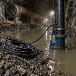
Sheath damage is normal on an industrial site. A tray edge, a dropped tool, rodent activity, a digger bucket and thermal movement all take their turn at the outer layer of a cable, and the damage itself is often small. What turns it into a serious fault is a damaged sheath that is never noticed, sitting in wet ground or in a duct that fills twice a year.
This guide is for buyers and maintenance engineers specifying cable for buried, ducted and outdoor routes, and for the people who have to find the damage when a circuit trips. It sets out how sheath damage becomes a ground fault, the locating methods and what each one can actually prove, the decisions to freeze before a fault occurs, and the tests that justify putting a repaired circuit back into service. Jacket and oversheath constructions sit in our weather resistant range, and the ageing behaviour behind a fault trend is covered in our note on cable ageing diagnostics.
How a Sheath Fault Turns into a Ground Fault
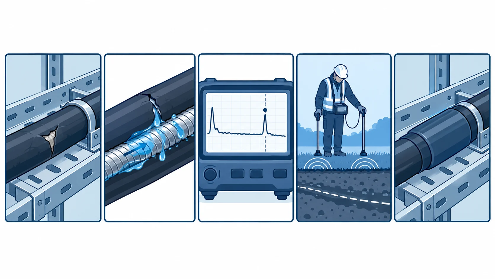
The sheath is a water barrier, not an electrical one by design. On most industrial cable the oversheath keeps moisture away from the insulation and the armour, and the armour or screen does the electrical work. Damage to the sheath opens the water path while the electrical performance stays normal, which is why the first symptom is usually a low insulation resistance on a wet day rather than a trip.
Water reaches the armour first. Once inside, moisture sits in the gap between the sheath and the armour, tracks along the cable length under gravity, and corrodes the armour at the low points. Corrosion products then swell, which opens the sheath further and lets more water in. That is the mechanism behind most long-run sheath failures, and it explains why the damage and the fault location are so often metres apart.
A ground fault is the electrical end of the story. When the water path reaches the insulation, or when corroded armour touches a conductive part of the route, the resistance from conductor to earth falls and the protection operates. By that point the original hole may be a hundred metres away, and the fault is being detected at the point where the route is earthed rather than where it was damaged.
Locating Methods Compared
The table sets out the methods a fault team chooses between: what each one can actually find, what to specify, the evidence to demand, what drives cost and time, and how each one leads a crew to the wrong place when the route records are poor.
| Method | What it finds | What to Specify | Evidence to Demand | Cost and Lead-Time Driver | How It Misleads |
|---|---|---|---|---|---|
| Insulation resistance and continuity | That a fault exists, and whether it is on the conductor or the sheath path | The test voltage, duration and the readings to be recorded per core and against armour | A signed test sheet with each core and the armour reading | Cheapest test on the list and needs only a basic set | A reading taken on a dry day that looks acceptable while the fault is still there |
| Time domain reflectometry | The distance to a low-resistance change, including a cut or a crushed section | The pulse velocity for the construction, which comes from the maker | The trace with the construction velocity and the scaling used | Modest equipment cost; the skill is in reading the trace | An assumed velocity that puts the mark tens of metres from the real damage |
| Sheath fault locating by step voltage | The point on the route where current leaves the sheath, for a wet or burnt-through sheath | The test current, the electrode spacing and the route length to be surveyed | A survey plot with the signal peak marked against the route chainage | Two people and a survey day, plus access along the route | Surveying by an approximate route alignment and finding the peak at the wrong structure |
| Acoustic or pressure-wave method | The discharge point, on a fault that breaks down under test voltage | The test voltage, the coupling arrangement and the noise environment | A location record with the surface mark and the distance from a known landmark | Slower than a voltage survey and dependent on background noise | Picking up a pump or a road vibration and marking a point that is not the fault |
| Thermal survey and physical inspection | The local hot spot or the visible damage, once the area is narrowed down | The survey condition, the load at the time and the route section to cover | Images with the load and the ambient recorded, plus a route sketch | Access and outage time rather than equipment | A survey taken at low load that shows nothing, and a conclusion that there is no damage |
Reading the Evidence: Resistance, Trend and Location
One reading proves very little. An insulation resistance figure taken on a wet day and one taken in a dry week can differ by an order of magnitude on the same cable, and neither tells you where the damage is. A trend of readings against weather and load is what turns a number into a diagnosis, and the method is set out in our note on insulation resistance testing.
Separate the conductor path from the sheath path. Test between core and core, core and armour, and armour and earth, and the pattern tells you whether the fault is in the insulation, in the sheath, or in the armour bond. A fault that only appears against armour is a different repair from one that appears against the cores, and the test sheet should record which reading failed.
Distance is only as good as the velocity. Any reflectometry result depends on the propagation velocity of the construction, which the maker should supply. Using a generic figure on a screened or armoured cable can put the mark tens of metres out, and a crew then digs in the wrong place and loses a day. Our note on in-service cable testing covers the wider question of what can be measured without an outage.
What to Freeze Before the Order Goes Out
Six decisions decide whether a fault is found in an afternoon or a week. Each is settled when the cable is bought and laid, long before anything goes wrong.
| Decision | What to State | Evidence to Attach | Cost of Leaving It Open |
|---|---|---|---|
| Sheath construction for the route | The jacket compound and thickness required where the route is buried, ducted or exposed | Construction sheet naming the oversheath and its thickness | A jacket chosen for the price and holed inside a season |
| Route record | As-built drawings with depth, duct positions, joints and landmarks at each change of direction | A digital route file handed over with the cable | A survey crew tracing a route by hand while the site stays down |
| Baseline test results | The insulation resistance and continuity readings taken at commissioning, per core | A signed commissioning test sheet with the weather and load noted | No way to tell a fault from a cable that was always marginal |
| Test points | Accessible test and earthing points at each end and at joints along the route | A layout drawing with the test point locations marked | Test sets connected at a panel and a survey that cannot reach the far end |
| Armour and screen bonding | Where the armour and screen are bonded, and how continuity is maintained across joints | The bonding detail plus the continuity result at commissioning | A fault that cannot be separated from a broken bond, so both ends are suspected |
| Repair accessories and spares | The joint, gland and oversheath repair system held for the route, with its rating | An accessory list matched to the cable construction and voltage | A repair that waits a month for parts while the circuit stays out |
Repair Method and Accessories
Match the repair to the damage, not to the desire for speed. A sheath nick that has not reached the armour is often repairable with a wrapped or heat-shrunk oversheath repair. Damage that has reached the insulation needs a joint, and damage that has corroded the armour over a length needs a section replacement. The three are different repairs with different ratings.
Use accessories rated for the same voltage and duty as the cable. This sounds obvious and is a regular failure point, because a joint rated for a lower voltage or a warmer ambient is available sooner and looks similar. Our note on MV cable termination testing covers how the accessory and the cable are proved together on a medium voltage route.
Repair the water path, not only the electricity. A repaired joint that restores conduction while leaving the oversheath open will fail again in the same duct, and usually within a season. Where the route is wet by nature, the repair should restore water blocking as well as insulation, and the sheath materials for that duty are set out in our note on cable sheath materials.
Look for the cause while the trench is open. A cable damaged at the same point twice is telling you about the route rather than the cable, and the cause is usually visible once the ground is open.
Proving the Repair: Tests and Records
Test after the repair, not after the backfill. Insulation resistance and continuity readings taken with the repair accessible cost almost nothing and catch a bad joint before it is buried. Rediscovering a failed joint under a reinstated surface is how a one-day repair becomes three.
Compare against the commissioning baseline. A repaired cable should return to something close to its original reading, and a figure well below the baseline suggests residual moisture or an incomplete repair rather than a successful one.
Verify the armour bond after the repair. Any joint or repair that opens the armour has to restore its continuity, and the reading should be recorded rather than assumed. The method is set out in our note on grounding and bonding verification.
Cost and Lead Time
A sheath repair kit is inexpensive and normally a stock item, which is why holding two of them for a buried route costs less than a single day of downtime. Joints and terminations sit in the middle of the range and vary widely with voltage and construction; a medium voltage joint is not a low voltage accessory and is not stocked everywhere. Section replacement carries the cost of the cable plus two joints and the excavation, and on a short damaged length it is often cheaper than an extended repair.
Where replacement cable is needed, copper is the largest element of the price and the movement between the fault and the purchase order is the main commercial risk, so ask how the copper element is calculated and how long the quotation holds. That mechanism is covered in our note on copper price and cable procurement.
When Locating a Sheath Fault Is Not the Answer
When the reading is marginal and the route is dry. A cable with a slightly reduced insulation resistance in a dry duct is worth monitoring rather than excavating. Digging up marginal cable costs more than the fault is worth and introduces a new risk at every joint.
When the fault is in the accessory. A fault that appears immediately at a termination or a joint is an accessory problem, and surveying the route for sheath damage will not find it. Test at the accessory first.
When the route itself is the fault. A cable damaged twice at the same duct entry needs the entry fixed, and a third repair in the same place is a waste of the second one. Fix the route and the cable problem stops recurring.
When the circuit is due for replacement. On an old route already due for renewal, the money spent locating an individual sheath fault is better put toward the replacement programme, and the comparison between a repair and a replacement is worth making before the survey begins.
RFQ Checklist
- The jacket compound and thickness for buried, ducted and exposed sections of the route
- As-built route drawings with depths, ducts, joints and landmarks, as a handover item
- Commissioning insulation resistance and continuity readings, per core and against armour
- Test and earthing points at each end and at every joint, marked on a layout drawing
- Armour and screen bonding arrangement, with continuity recorded at commissioning
- The propagation velocity for the construction, supplied by the maker for fault location
- A repairable oversheath system or joint kit held as a spare for each route type
- Accessories rated for the same voltage and temperature as the cable
- Water blocking restored at any repair in a wet route
- Post-repair test requirements, taken before backfill
- Route record update as a condition of completing the repair
- Copper basis and the validity window of the quoted price
Conclusion
A sheath fault is found by preparation rather than by equipment. The test sheet, the as-built route drawing, the bonding record and the spare joint kit are what turn a week of digging into an afternoon of work, and all four are bought or made when the cable is installed. Keep them and the fault is a maintenance event. Lose them and the same fault becomes a project.
Kexingyu Cable Group (KXYE) has manufactured cable in Quanzhou since 1996, including jacketed, armoured and ducted constructions for buried and outdoor industrial routes, supplied with construction sheets, propagation data and oversheath repair materials matched to the cable. Send us the route and the test results you have, and we will come back with the construction, the repair system and the tests that apply. A request for quotation is the fastest route.