Cable Recommissioning: Bringing Standby Circuits Back into Service

Quick Answer: Cable recommissioning is what stands between a standby circuit and a failed restart. A cable that has been idle for two years has not been tested by operation, and the things that go wrong in standing time are moisture, mechanical change and connections that have loosened without load. The circuit is usually energised on the day it is needed, which is the worst possible day to discover a low insulation resistance.
Introduction
Standby plant gets commissioned once and then sits. The generator, the pump set, the second feed and the fire pump circuit are all installed, tested and forgotten until the day they are needed, and the recommissioning check takes place at the moment when the answer has to be yes.
This guide is for buyers and maintenance engineers responsible for standby, redundant and seasonally idle industrial circuits. It sets out what standing time does to a cable, the checks that catch each problem, the decisions to settle when a circuit is mothballed rather than when it restarts, and the records that make the restart defensible. The in-service measurement side is covered in our note on in-service cable testing, and the ageing behaviour behind a falling trend is set out in our note on cable ageing diagnostics.
What Standing Time Does to a Cable
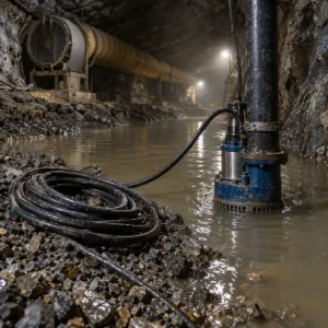
Moisture migration is the main mechanism. An idle cable is not automatically a dry cable. Glands that were never fully sealed, ducts that fill in the wet season, and a route that was flooded once during the shutdown all admit water, and where there is no load there is no heat to drive it back out. A cable that measured well at commissioning can measure badly after two wet winters.
Connections relax without load. Terminations are held by torque and by the pressure of the joint, and thermal cycling at first energisation is what settles them. A circuit that was commissioned, run briefly and then isolated can have a termination that has never been through a full thermal cycle, and that is the one that heats up on the first real load.
Mechanical change happens quietly. Supports corrode, tray covers come off, cable ties fail, and standing water in a duct lifts a cable off its supports. Rodents use idle enclosures, and a chewed sheath on an unused circuit can go unnoticed for years because nothing operates to reveal it.
Insulation resistance falls without anything failing. Absorption of moisture and the slow progress of ageing both reduce the reading without producing a fault. The reading alone does not say whether the cable is unfit, which is why the comparison against the commissioning baseline matters more than the absolute figure. Our note on insulation resistance testing covers the method and the corrections.
Pre-Start Checks Compared
The table sets out the checks available before a standby circuit is energised: what each one catches, what to specify, the evidence to demand, what drives cost and time, and how each one gives false comfort when it is treated as a complete answer.
| Check | What it catches | What to Specify | Evidence to Demand | Cost and Lead-Time Driver | How It Misleads |
|---|---|---|---|---|---|
| Insulation resistance and continuity | Moisture absorption, gross damage and a broken armour or screen path | The test voltage, the duration and the readings to be compared against commissioning | A signed test sheet with each core and the armour against the baseline | Hours of work and a basic test set | A reading above the acceptance minimum treated as proof that the cable is dry |
| Visual and mechanical inspection | Corroded supports, displaced cable, failed glands, rodent damage and standing water | The route sections to be walked, with photographs at each change of direction | A dated inspection record with images | Access and time rather than equipment | A sample inspection of the accessible section that misses the duct and the void |
| Water and sealing assessment | Water in ducts and enclosures, and glands that were never sealed | The sealing standard required, and drainage at each low point | Seal detail records plus the duct condition note | Small material cost and meaningful access time | Assuming a sealed gland because one was specified, without checking it was fitted |
| Thermal survey under load | A termination that heats up once real current flows | The load to be applied, the duration and the survey condition | Images with the load and the ambient recorded | Requires a load, which on a standby circuit takes planning | A survey taken at low load that shows nothing and closes the question |
| Functional and protection testing | Coordination and control problems that only appear on a real start | The sequence to be demonstrated, and the protection settings to be verified | A witnessed test record signed by both parties | The largest single item, because it needs the plant available | Testing the circuit in isolation and never proving it under real switching duty |
Restoring a Circuit Step by Step
Start with the record, not the test set. The commissioning baseline says what the cable looked like when it was new, and without it a reading has no context. A cable that was already marginal at handover is being judged against the wrong standard, and the record is what separates that from a genuine deterioration.
Walk the route before energising anything. The visual inspection finds the problems that no electrical test will show, and it is the cheapest hour on the job. Anything found should be photographed with a scale, because the repair decision will be made by someone who was not there.
Deal with moisture before applying voltage. Where a reading is low, the question is whether the moisture is at a termination, in a joint or along the route, and each has a different remedy. Applying a higher test voltage to a wet cable is not a fix, and it can make the position worse at the weakest point.
Then load it and prove it. A commissioning sequence that runs the circuit up to real load with a thermal survey at the terminations is what proves the connections. The record from that test becomes the new baseline, and the acceptance and witnessed testing arrangements are covered in our note on factory and site acceptance testing.
What to Freeze Before the Order Goes Out
Six decisions decide whether a restart is a morning’s work or a project. Each belongs to the day the circuit is mothballed, not the day it is needed.
| Decision | What to State | Evidence to Attach | Cost of Leaving It Open |
|---|---|---|---|
| Lay-up standard | How a circuit is left: sealing, isolation, drainage, labelling and the enclosure condition | A written lay-up procedure with a completed checklist per circuit | A cable exposed to two wet seasons and a restart nobody planned |
| Records at shutdown | The commissioning baseline plus the shutdown test result, per core and against armour | A test sheet filed with the circuit drawings | No reference point, so every later reading is judged against a generic minimum |
| Gland and enclosure sealing | The sealing standard for glands and enclosures on a standby circuit | The gland and seal details as installed | Water entering a gland that was specified as sealed but never proved fitted |
| Route protection and drainage | Drainage at each low point, and protection where plant traffic crosses the route | Route drawings with drainage and protection details | Standing water in a duct and a cable lifted off its supports by annual flooding |
| Spare parts and accessories | The gland, joint and termination materials held for each standby circuit | An accessory list matched to the cable construction and voltage | A restart delayed by a week waiting for a termination kit |
| Restart plan and responsibility | The checks, the sequence and the person accountable for signing the circuit back in | A restart procedure with named responsibilities and pass criteria | A circuit energised by whoever is on shift, on no evidence at all |
Bringing the Circuit Back: Sequence
Isolate, inspect, test, then energise. Doing the stages in that order costs nothing extra and prevents the situation where a circuit is energised to see what happens. On a standby circuit the temptation to switch on first is strong, because that is what it is for.
Test from the ends, not only from the panel. Readings taken at the supply end alone miss a fault on the far section, and on a long standby feed the two ends should both be recorded. Where the far end is not accessible, that becomes a design issue worth fixing while the circuit is still idle.
Re-torque the terminations to the maker’s figure. A termination that has been sitting unused has not been settled by thermal cycling, and the first real load is what reveals it. Re-torqueing to a recorded figure and noting it is a small job with a large return, and the thermal survey afterwards confirms it. The method is set out in our note on infrared thermography at commissioning.
Treat the restart as a new commissioning. The circuit has changed since it was first tested, and the restart record should be as complete as the original. Where an independent view is required, the arrangements are covered in our note on using a third-party commissioning agent, and the remaining life question that follows is covered in our note on cable life prediction.
Records and Acceptance
File the restart record with the circuit drawings. The value of a recommissioning record is that the next shutdown inherits it, so it belongs with the permanent circuit file rather than in a project folder. A record that cannot be found when the circuit is next mothballed has been wasted.
Note the ambient and the weather at the time of the test. Insulation resistance varies with moisture and temperature, and a reading without the conditions is not comparable to the last one. Two extra words on the test sheet make the trend usable.
Record what was repaired, and why. A gland replaced or a support corrected during recommissioning is a finding about the lay-up standard, and the pattern across several circuits is what justifies changing the procedure rather than repeating the same repair every cycle.
Cost and Lead Time
Testing and inspection are labour, access and a modest amount of equipment, and they are the cheapest part of a restart. Sealing and drainage work costs little in material and a lot in access, so it is best combined with another intervention on the route. A termination or section replacement found at restart carries the accessory cost plus the outage, and it is the reason a standby circuit should be tested on a planned date rather than on the day it is needed.
Where replacement cable or accessories are needed, copper is the largest element of the price, so ask how the copper element is calculated and how long the quotation holds. A part ordered in an emergency during a restart pays a premium that a planned purchase does not, which is the commercial argument for testing standby circuits on a schedule. That mechanism is covered in our note on copper price and cable procurement.
When a Full Recommissioning Test Is Not the Answer
When the circuit has been in service. A circuit that is cycled regularly is commissioning itself, and the value of a full test is much lower than on a circuit that has sat idle. Put the effort where the standing time is longest.
When the reading is low but the route is dry. A single low reading on a dry circuit is worth repeating with the ends cleaned and the conditions recorded before any repair is planned. Contamination at a termination is a common cause and a cheap one to remove.
When the circuit is due for replacement. Money spent proving a cable that is scheduled for renewal is better put toward the renewal, and the replacement programme is a legitimate reason to test less rather than more.
When the load is not available. A thermal survey without load proves very little, and pretending otherwise closes a question that is still open. Where the load cannot be applied, the terminations should be inspected and re-torqueed instead, with the survey scheduled for the first real run.
RFQ Checklist
- A written lay-up procedure for each standby circuit, with a completed checklist
- Commissioning and shutdown insulation resistance readings, per core and against armour
- Continuity of armour and screen, recorded at both ends of the route
- The sealing standard for glands and enclosures, with the detail as installed
- Drainage at each low point, and protection where plant traffic crosses the route
- A dated route inspection record with photographs at each change of direction
- Termination re-torque values from the maker, with the figure recorded after the work
- The load to be applied for the thermal survey, and the survey condition
- Gland, joint and termination spares held for each standby circuit
- A restart procedure with named responsibilities and pass criteria
- Witnessed functional and protection testing arrangements, where required
- Copper basis and the validity window of any quoted replacement price
Conclusion
Cable recommissioning is mostly about having decided things earlier. A circuit left with sealed glands, drainage, a stored baseline reading and a restart procedure comes back in a morning, and the evidence for switching it on is already in the file. The same circuit left to itself comes back with a low reading, a wet duct and no reference point, and the decision to energise becomes a guess.
Kexingyu Cable Group (KXYE) has manufactured cable in Quanzhou since 1996, supplying industrial standby and redundant circuits with the construction data, sealing arrangements and commissioning records that make a restart defensible. Send us the circuits and the shutdown history, and we will come back with the checks, the accessories and the records that apply. A request for quotation is the fastest route.