
Buying Humanoid Actuator Cable: Joint Duty, Bend Radius and What to Specify
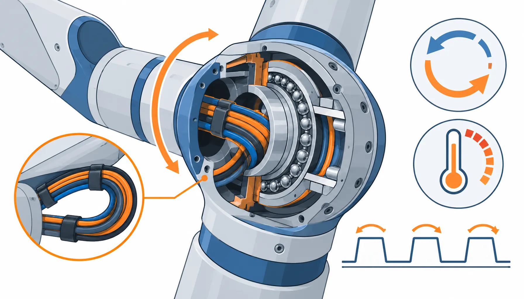
Quick Answer: The actuator joint is the hardest-worked cable run on a humanoid. It sits in the smallest envelope, in the warmest air, reversing thousands of times per hour with no room for a service loop. This guide sets out the duty figures to declare for each joint, the bend and twist evidence to demand, and the ten decisions to freeze before the order.
Introduction
Most coverage of humanoid cabling, including our own note on the humanoid robot cable category, treats the machine as a whole. This one goes to the component with the worst duty per cubic centimetre: the rotary actuator joint that drives the hip, the knee, the shoulder, the elbow or the wrist.
Joint modules usually arrive from the actuator supplier as sealed units, and it is tempting to treat the cable inside as their problem. It isn’t. The cable specification inside a joint is written by the buyer, it drives the module’s service life harder than the motor rating does, and it is one of the few places where a ten-minute requirement, stated early, prevents a twelve-month warranty argument later.
What a Joint Does to Its Cable
An actuator joint does not sweep like an industrial arm. It reverses constantly through a partial arc, braking at each end, at a rate no datasheet axis rating describes. A walking gait loads the hip and knee with thousands of small bidirectional movements per hour, and the cable wrapped around the joint axis experiences every one of them. The count per hour is modest on paper; the count per year is not, and neither is the wear.
The envelope is the second pressure. Humanoid joints are packaged tight, and the cable often leaves the housing through a radius the mechanical designer had left over, not one chosen for the cable. A bundle bent below its stated minimum looks fine on the bench and loses strands in the field, which is why the bend figure has to be negotiated before the housing is final. The mechanics are set out in our note on cable minimum bend radius.
Heat is the third. The joint can is a small enclosed volume with a warm motor in it, and the cable spends its life near that temperature ceiling. Inside the same bundle sit power conductors, a brake pair and encoder signals, and the encoder pair is the first to complain when insulation drifts. The temperature mechanics are covered in our note on thermal paths inside robot arms, and the signal side in our note on encoder cable.
Declare Duty per Joint, Not per Machine
A single “humanoid duty cycle” figure hides the spread that matters. The knee sees deep arcs at walking frequency; the wrist sees small amplitudes at high frequency; the shoulder sees long dwells between bursts. Each profile loads the cable differently, and each deserves its own line in the requirement: reversals per hour, arc amplitude, dwell time and ambient temperature at the joint.
Put those numbers in the actuator module purchase order, not in a general machine specification. When the figure is contractual, the supplier’s flex data has to answer to it, and a module that fails early becomes a documented claim instead of a debate. When the figure is missing, the module ships with whatever bundle was already qualified, which is usually a robot-grade cable rated for a much larger radius than your joint offers.
The routing inside the joint deserves the same treatment. A short service loop, ten to twenty millimetres of slack arranged so the loop flexes rather than the terminal, converts joint travel into controlled bending and keeps the solder joints still. The pattern is the same one used at industrial robot axes, described in our note on routing cable through robot joints.
Weight, Stiffness and the Torque Budget
Every gram inside the joint is a gram the actuator accelerates on every movement, and a gram the battery pays for at the end of the shift. That makes the cable’s weight per metre a real specification line rather than a footnote. State the budget in grams per metre at the finished harness level, conductor through jacket, and hold the supplier to it; a bundle that arrives fifteen percent heavier than quoted has quietly spent torque someone else had allocated.
Stiffness matters as much as mass. A stiff bundle resists the joint’s motion and can introduce settle or overshoot at the end of each arc, which the controls team will eventually trace back to the harness. Softer jacket compounds and finer conductor stranding cost a little in abrasion tolerance and buy back motion quality, and on a machine whose whole point is smooth human-adjacent movement, that trade usually prices out in favour of the softer build.
Keep the conductor sizing honest at the same time. Oversizing power conductors because the joint “might” see peak current is how bundles gain weight without gaining life, and the encoder pair, which sets the signal budget, is usually a much lighter requirement than the power side. Size each element to its measured load and let the schedule, not habit, decide the mass. Where the slack in a loop is part of the arrangement, the tolerance on that length belongs on the drawing too, along the lines set out in our note on cable length tolerance.
The Decision Table: Four Constructions for Actuator Joints
| Construction | What to specify | Evidence to demand | Cost and lead time | Where it fails |
|---|---|---|---|---|
| Standard high-flex round bundle | Flex cycles at the joint's actual radius, plus the amplitude | A flex test run at your radius, not a generic figure | Lowest cost, shortest lead time | Strand fatigue where the radius undercuts the test condition |
| Torsion-rated bundle | Twist degrees per metre, direction and reversals per hour | A twist test at your angle and your reversal count | Higher unit cost, longer lead time | Over-buying twist rating for joints that only flex |
| Low-profile flat build | Thickness, minimum bend axis and the fixed direction of wrap | A flex record with the flat face oriented as installed | Medium cost, moderate lead time | Twisting out of plane where the route was assumed fixed |
| Hybrid power-signal composite | Conductor schedule, separation rules and the shield plan | A crosstalk or immunity record for the encoder pair | Higher cost, custom lead time | Field changes that force a full custom rebuild |
| Overmolded joint harness | Overmold geometry, exit angle and the strain relief detail | A pull and flex record on the molded assembly | Highest tooling cost, longest first lead | Paying mold cost before the joint design has frozen |
Bend, Twist and the Evidence That Settles Arguments
Two figures decide most actuator cable disputes, and neither is the conductor size. The first is flex life at the joint’s installed radius, tested at the amplitude and frequency the joint actually produces. The second is twist tolerance, tested in both directions, for joints where the cable wraps the rotating axis. Ask for both as test records with the method stated, because a datasheet number without a method is a sentence, not a specification. The test mechanics are described in our note on cable flex testing methods.
Close the gap with hardware. A sample assembly, built to the production drawing and flexed on a bench rig that reproduces the joint’s arc, settles in a week what a datasheet argument would settle never. The acceptance route, from sample build to signed approval, is set out in our note on robot cable sample testing.
What to Freeze Before the Order
| Item | What to state | Evidence to attach | Cost of leaving it open |
|---|---|---|---|
| Reversal count | Reversals per hour and per year, per joint | A gait or motion study, not an estimate | A flex rating nobody can verify |
| Arc amplitude | Degrees of travel and dwell per joint | A motion profile from the controls team | Cable rated for the wrong motion shape |
| Installed radius | The actual radius at the housing exit | A dimensioned drawing of the joint can | Strand fatigue inside a sealed module |
| Twist duty | Degrees per metre, direction, reversal rate | A twist test record at the declared duty | Unwinding conductors at the axis |
| Conductor schedule | Power, brake and encoder pairs, and their sizes | A schedule agreed with the drive vendor | Reopening the bundle at the worst moment |
| Temperature | Joint ambient at continuous duty, and peak | A thermal record from the module test | Insulation ageing at the motor can |
| Service loop | Loop length, shape and fixing points | A drawing marking the loop on the harness | Terminal joints carrying the flex instead |
| Exit and strain relief | Exit angle and the relief method at the housing | A pull test record on the finished harness | Lead breakage at the gland, not in the cable |
| Sample approval | Which assembly is the approved reference | A signed sample approval from the pilot build | Production units differing from the tested one |
| Spares per station | Harness assemblies held per test station | A spares list agreed with production | A station down waiting on one harness |
When a Joint-Rated Bundle Is Not the Answer
When the joint rotates continuously in one direction. A wrap-around cable handles partial arcs, not endless rotation. Where the axis keeps turning, the answer is a rotary transfer, and the trade-offs are set out in our note on slip rings and rotary unions. Paying for a thicker twist-rated cable does not buy what a slip ring buys.
When the failures sit at the connector. If the record shows lead breakage at the gland or fretting at the contact, a better cable changes nothing. Fix the exit geometry and the contact interface first; the failure modes are described in our note on why robot connectors fail.
When the program is still at prototype volume. A custom overmold or a private conductor schedule costs tooling money that a fifty-unit program cannot recover. Buy a qualified standard bundle, document the joint duty precisely, and keep the customisation for the design freeze. Where similar small-space duty appears elsewhere on the machine, our note on dexterous hand wiring takes the same position.
When the joint is a spare for an existing fleet. Matching the installed construction, down to the exit angle, beats upgrading one joint in isolation, because a mixed harness set turns every future order into an identification exercise. Upgrade the whole fleet at a revision boundary, or don’t upgrade at all.
RFQ Checklist
- Reversal count, arc amplitude and dwell stated per joint, from a motion study
- Installed bend radius dimensioned on the joint housing drawing
- Twist duty stated in degrees per metre, direction and reversals per hour
- Flex and twist figures supplied as test records at the declared duty, with methods
- Conductor schedule for power, brake and encoder pairs agreed with the drive vendor
- Joint ambient temperature at continuous duty and at peak declared
- Service loop length and fixing points marked on the harness drawing
- Exit angle and strain relief method stated, with a pull test record
- Sample assembly approved in writing before production release
- Spare assemblies held per station, built to the approved revision
Conclusion
Actuator cable is bought on numbers only the buyer can supply: reversals, amplitude, installed radius and joint temperature, each stated per joint rather than per machine. With those figures in the purchase order, the construction argument shrinks to evidence, and a module supplier has something concrete to qualify against. Without them, every joint ships with whatever bundle was nearest at hand, and the fleet writes the specification by failing.
Kexingyu Cable Group (KXYE) builds high-flex and torsion-rated bundles for compact rotary duty and supplies them with the test records that make the evidence chain complete. Send us the per-joint duty figures and the housing drawings, and we will return constructions, bend data and sample assemblies for bench qualification; the fastest route is a request for quotation.


