Cable Laying Method Selection: Matching the Route to the Purchase
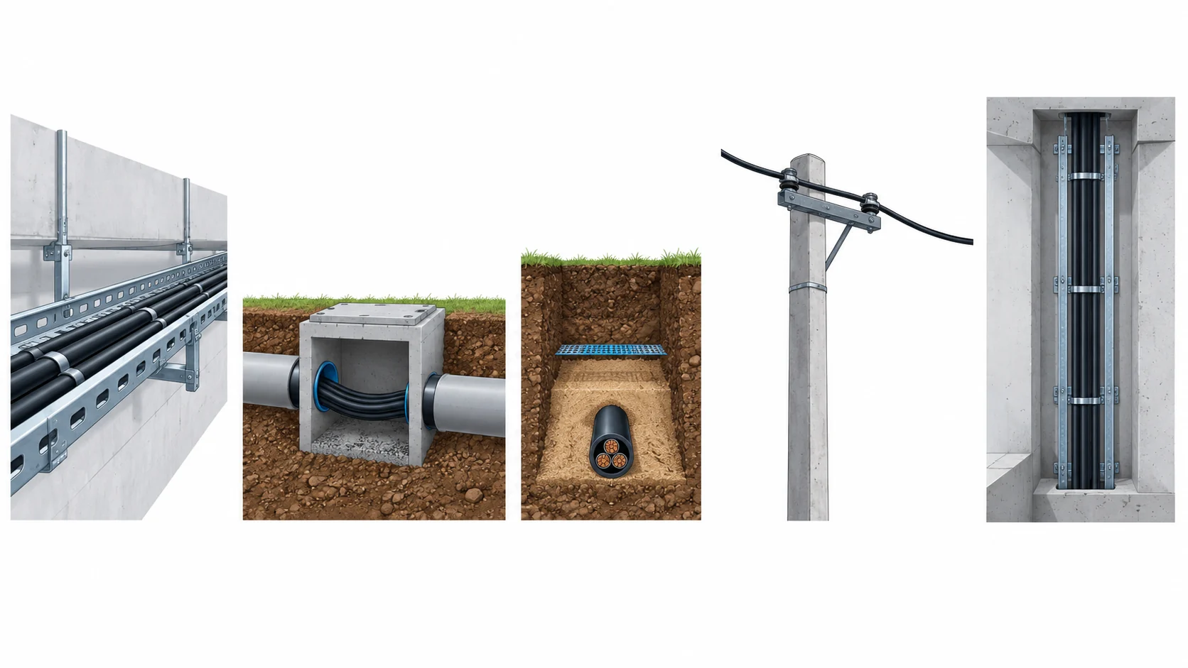
Quick Answer: The cable laying method is a design decision that lands in the purchase, because tray, duct, buried, aerial and riser routes each demand a different sheath, armour, handling limit and derating basis. Choosing the method after the cable is bought is how projects end up with an armoured cable on a clean tray or an unarmoured cable in a trench. Fix the method per route section first, then let the cable specification follow it.
Introduction
On paper a route is a line between two points. In practice it is a tray, a duct, a trench, a pole or a shaft, and each of those environments puts a different demand on the cable long before the electrical load is considered.
This guide is written for the buyer raising the requisition. It sets out the five common laying methods and what each one requires, how the choice changes the order and the price, and what to freeze so the cable and the route agree. Where a route ends up in a shaft, our note on the vertical riser and shaft cable covers that case in detail.
Why the Laying Method Decides the Cable
Mechanical duty comes first. A cable on a clean indoor tray is protected and rarely touched. The same cable in a trench is walked on, backfilled over and dug near, and in a duct it is pulled through bends with the whole drum tension behind it. The method sets the mechanical duty, and the mechanical duty sets the armour and the sheath.
Thermal duty follows. The method also sets how the cable sheds heat. Free air and a ventilated tray cool well; a duct, a densely grouped tray and a burial depth do not. The derating that comes out of the method is often the reason a route needs a larger cross-section, which is covered in our note on cable derating factors.
Then the handling limits. The way a cable is installed sets the minimum bend radius and the maximum pull tension it has to survive, and those are checked against the construction rather than assumed. A cable that meets the electrical requirement can still be wrong if it cannot be pulled round the bends the route actually has.
Then the maintenance and access. A route that can be inspected and repaired is a different purchase from one that is sealed. Buried and ducted routes need protection and marking because access is expensive, while a tray route can be opened on a normal working day.
The Five Laying Methods and What Each Demands
The table sets out each common method, where it fits, what to state in the specification and how the route fails when the method was chosen on price alone.
| Laying method | Where it fits | What to Specify | Evidence to Demand | Cost and Lead-Time Driver | How It Fails |
|---|---|---|---|---|---|
| Tray and ladder | Plant rooms, racks, indoor distribution, accessible routes | Tray load and spacing, grouping count, fire performance of the tray system | Tray loading data and the grouping derating applied | Tray and supports are civil cost; the cable itself is usually standard | An overloaded tray that derates every circuit on it as more are added |
| Duct and conduit | Road crossings, congested areas, routes where access must be closed | Duct size and fill, number of bends, draw pits and the pull length | Duct fill calculation and bend data against the pull plan | Duct installation and draw pits, plus slower cable pulling | A duct run with too many bends that cannot be pulled without damage |
| Direct buried | Yards, farms, perimeter routes, open ground where a trench is acceptable | Burial depth, bedded sand, protection tiles, warning tape and soil conditions | An installation drawing with depth, bedding and marking called out | Civil cost of the trench, plus an armoured cable | A route dug through later because no warning marker was laid |
| Aerial and catenary | Long open spans, temporary supplies, crossings where trenching is uneconomic | Span and sag, the messenger or support, wind and ice loading, UV exposure | Loading data for the span and the supported cable | Support structures and fittings, plus a UV-stabilised construction | A span that sags into reach, or a jacket that chalks in strong sunlight |
| Riser and shaft | Multi-storey buildings, towers, deep shafts and tall plant | Vertical support spacing, fire stopping at each floor, expansion and weight | Support spacing and fire-stop detail against the shaft design | Support cleats and fire stops, and a construction that tolerates the height | A riser that loads its own terminations, or a shaft that is not fire-stopped |
What Changes in the Order When the Method Changes
Armour or not. A buried or ducted route usually justifies an armoured cable, because the mechanical duty is real and hard to inspect. Our note on armoured versus unarmoured cable sets out where the armour earns its cost and where it is weight without benefit.
The sheath compound. Buried routes meet soil, water and abrasion; aerial routes meet sunlight and wind. Both push the sheath choice away from a plain indoor jacket, and both are covered by the wider family in our note on abrasion resistant cable jackets and the outdoor exposure guidance that travels with it.
The derating basis. The method sets the reference figure the ampacity is taken from, so a change from tray to duct changes the calculation, not just the installation. Two identical loads on two different methods can need two different cross-sections.
The drum and the joint strategy. A duct run with draw pits allows joints at the pits, while a buried run prefers long drums and no joint at all. The method therefore drives the drum schedule as much as the drum schedule drives the joints.
The accessories. Glands, cleats, fire stops and support spacing all follow the method, and buying them on the cable order rather than separately keeps the delivery coherent. The wider list is set out in our note on the cable damage and wear patterns that a badly matched method produces.
What to Freeze Before the Order Goes Out
Six clauses turn the method choice into a purchase that fits the route.
| Decision | What to State | Evidence to Attach | Cost of Leaving It Open |
|---|---|---|---|
| Method per section | The laying method for every section of the route, not a single method for the whole run | A route drawing marking tray, duct, buried, aerial and riser sections | A cable that fits one section and is wrong on the others |
| Mechanical protection | Armour, duct, tile or conduit where the route is exposed to digging or traffic | A protection schedule with depth and containment called out | Damage from a spade or a vehicle that nobody planned for |
| Derating basis | The reference figure for each method and the corrections applied | A derating sheet naming the method for each circuit | A cable sized on the wrong method and left short of capacity |
| Bend and tension limits | The tightest bend and maximum pull tension, checked against the construction | Bend and tension data for the construction offered | A pull that stretches or kinks the cable before it is energised |
| Support and fire stop | Support spacing on risers and fire stopping at every floor or wall | A support and fire-stop detail for the shaft or building | A riser that loads its own terminations, or a shaft that is not sealed |
| Marking and records | Warning tape, route markers and as-built records for the sealed sections | As-built drawings and photographs of the sealed route | A future excavation that finds the cable the hard way |
Pulling, Bending and the Limits That Decide
Every method has a pull and a bend, and these are the two figures that most often rule out a construction the buyer had already chosen. A tray route with a tight turn, a duct with four bends and a riser that changes direction each impose a minimum radius the cable has to meet. The figure is checked against the construction, not assumed from the size, and the discipline is set out in our note on the cable minimum bend radius.
Pull tension matters as much on duct and buried routes, where the drum sits at one end and the cable is dragged the length of the run. Excessive tension stretches the conductor and damages the sheath, and it shows up later as a resistance fault rather than as obvious damage. State the maximum tension the route allows and confirm the construction can take it, and plan the lubricant and the pull direction before the day of the pull rather than during it.
Support spacing is the third limit, and it is a riser and aerial question rather than an indoor one. A cable that supports its own weight over a span settles and loads its terminations, and a riser that is cleated at the wrong pitch does the same. Support spacing belongs in the installation detail, and the cable construction has to be checked against it.
Constructions and What They Cost
The method changes the construction, and the construction changes the price in ways that go well beyond the cable. Our seismic bracing for cable trays note shows how the tray system and its bracing can dominate a route’s cost in a seismic region, while the cable itself stays standard. Choosing a method that avoids the heaviest containment can be the larger saving.
Standard tray cable is the cheapest and quickest, and it suits accessible indoor routes where little can reach it. Armoured and ducted constructions add metal and containment and run on a longer line, but they remove the need for protection that would otherwise be rebuilt after every incident. Aerial and riser constructions carry the loading and support design with them and are usually made to order. Copper and steel drive the material cost in every case, and where a route is short on space, a dense tray changes the derating as well, as our note on the high-density cable tray explains.
Incoming Inspection and What to Record
Against the method schedule. Check that the construction delivered answers the method for each section: armour where it is buried, a suitable jacket where it is exposed, and the right derating basis where it is grouped.
Before the pull. Inspect the drum, the cable ends and the first metres of the coil, because a buried or ducted pull is expensive to repeat. Confirm the lubricant and the pull plan are agreed.
During and after the pull. Record the pull tension where the route is long, and inspect the cable at the far end and at every draw pit for sheath damage. Photograph anything that looks wrong before the route is closed.
Record the as-built route. Keep drawings and photographs of the sealed sections, with depths and marker positions. That record is the only protection the next excavation has, and it is what a future repair works from.
When the Cheapest Method Is Not the Answer
When the route cannot be reached again. A cheap buried route that nobody can find a decade later is not cheap. Where access is hard, the containment or the marking that makes the route findable is worth more than the cable premium it avoids.
When the tray is already full. Adding cable to a dense tray to avoid a new duct saves containment money and costs derating on every circuit, sometimes for the life of the plant. The two have to be compared, not assumed.
When the span is too long for the support. An aerial route chosen to avoid trenching can need structures and loading design that cost more than the trench. Where the span is marginal, the containment is the decision rather than the cable.
When armour is added to a route that does not need it. The opposite mistake is just as common: armouring a clean indoor tray route, adding weight, stiffness and cost, and making the pull harder than it needed to be. Match the protection to the threat the method actually creates.
RFQ Checklist
- The laying method for every section of the route, with lengths
- Armour, duct, tile or conduit required, and by which section
- The reference figure and derating basis for each method
- Tightest bend and maximum pull tension for each route section
- Draw pit or joint bay positions, and the drum schedule they imply
- Support spacing on risers and aerial spans, with loading data
- Fire stopping at floors and wall penetrations, and who supplies it
- Jacket compound required for sun, soil or abrasion exposure
- Warning tape, route markers and as-built records for sealed sections
- Accessories for the method: glands, cleats, supports and stops
Conclusion
The laying method is not an installation detail that follows the cable; it is a purchase decision that precedes it. Fix the method per section, read off the mechanical and thermal duty it creates, and let that set the armour, the sheath, the derating and the handling limits. The armoured cable on a clean tray and the unarmoured cable in a trench are the two ends of the same mistake, and both are bought by choosing the cable before the route.
Kexingyu Cable Group (KXYE) has manufactured cable in Quanzhou since 1996, supplying tray, ducted, buried, aerial and riser constructions with the armour, jacket and handling data that each method demands, and support and accessory schedules to match. Send us the route drawings with the methods marked, and we will come back with the constructions, the derating basis and a delivery plan against your programme. A request for quotation is the fastest route.