
Humanoid Torso Wiring: Managing Twist and Flex Through the Spine
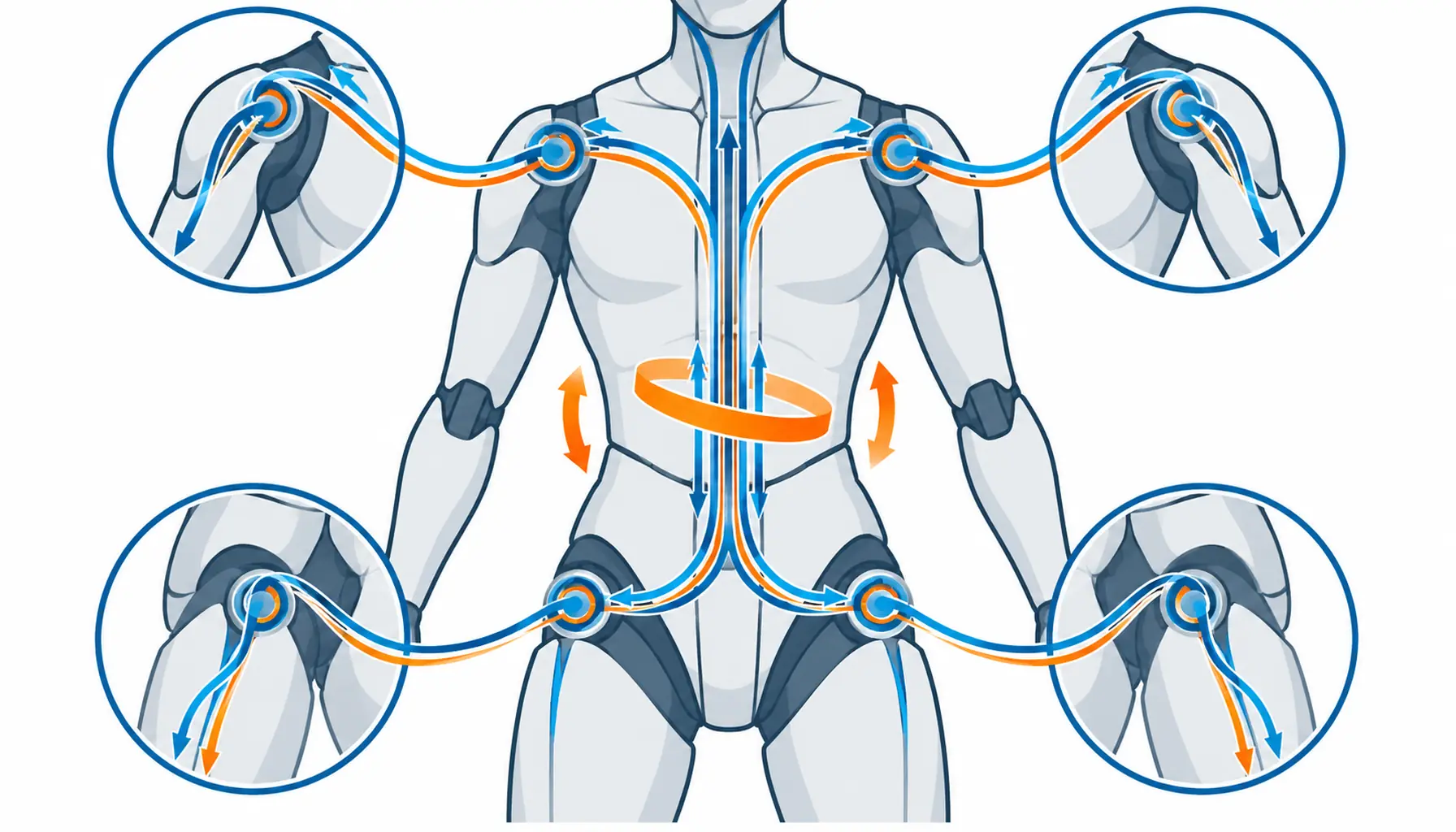
Quick Answer: The waist is the only joint on a robot that twists and bends at the same time, and the torso harness crosses it with every step and turn. This guide sets out the compound motion figures to declare, the routing strategies worth comparing, and the ten decisions to freeze before the order.
Introduction
Limb cabling has its own logic, covered in our note on humanoid actuator cable, and the machine-level picture lives in our note on the humanoid robot cable category. The torso sits between them, and it is the part of the harness where everything meets: power going down from the battery, sensor and drive signals going up from the legs, and all of it crossing a waist that rotates.
For a buyer, the torso is also where routing decisions made quietly by whoever draws the harness first become permanent. A bundle that crosses the waist badly does not fail dramatically; it loses strands slowly, reads as an intermittent fault nobody can locate, and gets redesigned at the worst possible moment. Declaring the routing strategy early is cheap. Doing it after the frame is cast is not.
What the Waist Does to a Bundle
Most robot joints bend. The waist twists. Combined with the lean and sway of a walking gait, a bundle crossing the waist experiences rotation about its own axis at the same time as bending about several others, and that compound motion is the most damaging combination a flexible cable can be asked to survive. Bend-only constructions unwind quietly under torsion; torsion-rated constructions exist precisely because this case is common enough to deserve its own engineering.
Count the duty before choosing one. Degrees of waist rotation per cycle, cycles per hour, and the bending amplitudes that arrive simultaneously, all belong in the requirement as figures rather than adjectives. A torso harness quoted against “moderate waist motion” is quoted against whatever the supplier imagines, and the imagined version is always gentler than the real gait.
The direction of the design matters too. Torsion accumulates over cycles in a preferred direction on many machines, because the task favours one way of turning. A construction qualified for symmetric twist can still fatigue under a one-sided duty, so the requirement should state whether the motion is balanced and let the supplier prove symmetry if they claim it. The construction mechanics are set out in our note on torsion cable construction.
Temperature sits quietly behind all of this. The torso warms under continuous walking and cools between shifts, and a jacket that was qualified at room temperature is not the jacket that works at the end of a hot shift followed by a cold night. State the operating band, including the parked extremes, so the compound duty gets tested at the temperatures it will actually meet.
Split the Route: What Rides Through the Waist and What Doesn't
The cheapest torsion duty is the one the harness never crosses. Before sizing anything, sort the runs by necessity: power and signals that genuinely connect torso to limbs must cross the waist, but many runs can be split at the hip or shoulder into local loops that never leave their segment. A leg module that carries its own drive and encoder wiring, terminating at a hip-level break, removes its channels from the waist bundle entirely, and every run you relocate is a run that stops fatiguing.
That split is also the service story. Harnesses that funnel everything through one central trunk are tidy to look at and miserable to maintain, because no single circuit can be inspected or replaced without touching the trunk. Distributing the routing costs a little mass and buys testable segments, and the trade between integrated internal wiring and separable external sections is examined in our note on internal wiring versus external dress pack.
What remains in the waist trunk deserves explicit slack design. A service loop arranged at the rotation axis, with the loop flexing rather than the terminations, converts compound motion into controlled bending. The loop’s length, fixing points and tolerance belong on the drawing, not in the assembler’s judgment, because a loop that was dimensioned by habit fails by habit.
Separation and Shielding Inside One Channel
A torso trunk is an electromagnetic neighbourhood, and the neighbours are badly matched. Leg drive currents share the channel with encoder pairs and sensor lines that read a few millivolts, and the distance between them is whatever the channel geometry allows. Left to arrangement by assembly, the sensitive pairs end up wherever there was room, and the result appears later as sensor faults that move with load and vanish on the bench.
The answer is a separation plan stated at schedule level: which circuits are noisy, which are sensitive, and which layer or position each takes inside the channel. Where a shield is part of the plan, its termination matters more than its coverage, because a shield that ends in a pigtail behaves like an antenna at exactly the frequencies that matter. The grounding and shielding practice for moving cable runs is set out in our note on EMC for moving cable and grounding.
Verify the plan with hardware rather than trust. A channel mock-up with the real circuits powered at duty, and the sensitive lines read for noise, costs a day and answers the question permanently. Writing the acceptance limit for that check into the requirement is what makes the supplier’s separation plan a commitment instead of a drawing annotation.
The Decision Table: Four Routing Strategies for a Humanoid Torso
| Strategy | What to specify | Evidence to demand | Cost and lead time | Where it fails |
|---|---|---|---|---|
| Single central waist trunk | Compound twist and bend duty for the whole bundle | A combined twist-plus-bend cycle record | Lowest mass, standard lead time | One trunk failure takes every circuit with it |
| Split dual trunks, left and right | Which circuits ride each side and the duty per side | Duty records per trunk, not per machine | Medium mass, moderate lead time | Imbalance if one side carries the noisy pairs |
| Local loops at hip and shoulder | Which runs terminate at each segment break | A schedule of what does and doesn't cross the waist | Higher design effort, lower lifetime cost | Loops that drift back into the trunk over revisions |
| Torsion-rated through-spine channel | Channel geometry, cable outside diameter and fill | A flex and torsion record at the channel radii | Higher part cost, longer lead time | Fill creep as late circuit additions squeeze in |
Constructions That Survive Compound Motion
Whichever row wins, the specification keeps one shape: compound duty figures for what crosses the waist, a declared list of what doesn’t, and slack drawn rather than guessed. Suppliers can quote against that shape, and the strategies stay comparable when the second supplier enters the program.
What to Freeze Before the Order
Torsion-rated builds differ from ordinary flexible cable in how they lay up their elements, and the differences show up exactly where a torso harness lives. Shorter lay lengths, element balancing and softer jackets let a bundle absorb rotation about its axis without unpacking, and the construction details are compared in our note on torsion cable construction, with the application patterns in our note on torsion cable in rotating applications.
Where the waist duty is dominated by flex with only modest twist, a continuous-flex construction may carry the run at lower cost, and the honest comparison between the two families is the subject of our note on continuous flex versus drag chain cable. The error to avoid is buying torsion rating as insurance: an over-rated construction is stiffer than the duty needs, and stiffness loads the terminations it was meant to protect.
Bend radius claims need the same scepticism at the torso as anywhere. The waist channel rarely offers the radius the cable would choose, and a bundle quoted at a radius the frame cannot provide is a failure scheduled in advance. Fix the radii on the routing drawing, then demand flex evidence at those radii, following the logic set out in our note on cable minimum bend radius.
When a Central Trunk Is Not the Answer
| Item | What to state | Evidence to attach | Cost of leaving it open |
|---|---|---|---|
| Waist duty | Twist degrees, bend amplitudes, cycles per hour | A motion study, not a description | A construction rated for an imagined gait |
| Direction balance | Whether twist is symmetric or one-sided | Cycle counts per direction from the logs | Fatigue that appears only in production units |
| Crossing list | Which circuits cross the waist, which don't | A schedule agreed with the controls team | A trunk that grows back run by run |
| Strategy | Which of the four routing rows the program picks | A routing drawing showing the split | Quotes for different machines |
| Channel radii | The actual radii the frame provides | Dimensioned drawing of each channel | Strand fatigue inside the spine channel |
| Service loops | Loop length, position and fixing points | A drawing marking each loop | Terminations carrying the flex instead |
| Segment breaks | Where each limb and torso section disconnects | A drawing marking every break | Inspection that requires trunk surgery |
| Separation | Which pairs are sensitive, which are noisy | An immunity record for the sensitive pairs | Sensor faults traced to the trunk |
| Fill rule | Maximum channel fill, now and for additions | A fill calculation with headroom stated | Late circuits crushing the early ones |
| Sample approval | Which harness build is the approved reference | A signed sample report with the duty test | Production units differing from the tested one |
RFQ Checklist
When the machine will be serviced in the field. A single trunk that ties every circuit through one channel turns any local fault into a whole-torso investigation. Field-serviced machines want segments that can be tested and swapped alone, and the design logic is the one set out in our note on designing robot cabling for serviceability.
When the waist barely rotates in the actual task. Many demo and logistics duties turn the torso rarely, and a torsion-rated central bundle is then mass and stiffness paying for motion that never happens. Measure the task first, and let the numbers, not the machine category, pick the construction.
When the program is at prototype volume. A through-spine channel with custom fill and fixed radii assumes a frozen design. Prototype machines get further with split bundles and generous loops, then commit to the channel when the gait and the circuit list have stopped moving.
When the faults are at the connectors. If the failure record shows intermittents at breaks rather than conductor fatigue in the runs, no routing strategy will fix it. The contact interface is the suspect, and its failure physics are described in our note on why robot connectors fail. Fix the joints first, then judge the routing.
Conclusion
- Waist twist degrees, bend amplitudes and cycles per hour stated from a motion study
- Direction balance of the twist declared, with per-direction cycle counts
- A crossing list naming which circuits pass the waist and which terminate at segment breaks
- Channel radii dimensioned on the frame drawing, with flex evidence at those radii
- Service loop length, position and fixing points marked on the routing drawing
- Segment break locations agreed for inspection and swap access
- Separation plan for sensitive pairs, with an immunity record
- Channel fill calculated with headroom for late additions
- Sample harness approved in writing, tested at the declared compound duty
- Spare trunk and loop assemblies held per station, built to the approved revision


